GE PP9830SJSS Use and Care Manual - Page 17
INSTALLATION INSTRUCTIONS, Installation Instructions, CABINET PREPARATION CUTOUTS
 |
View all GE PP9830SJSS manuals
Add to My Manuals
Save this manual to your list of manuals |
Page 17 highlights
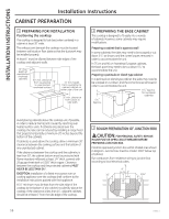
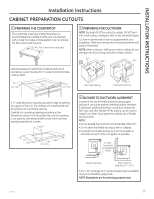
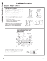
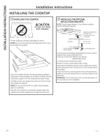
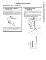
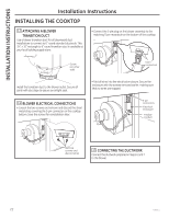
INSTALLATION INSTRUCTIONS Installation Instructions CABINET PREPARATION CUTOUTS 4 PREPARING THE COUNTERTOP The countertop must have a deep flat surface to accommodate the cooktop and the vent. Countertops with a rolled front edge and backsplash may not provide the flat surface area required. 25" min. flat surface area required Clearance between inside front of cabinet and rear of countertop cutout must be 205ø8" in order to accommodate cooktop depth. 5 PREPARING FOR DUCTWORK NOTE: Ductwork MUST be vented to outside. DO NOT vent into a wall, ceiling, crawlspace, attic or any concealed space. Cut hole in cabinet wall or floor as appropriate for your installation. Make sure exhaust duct is located between wall studs or floor joists. NOTE: When cutting or drilling into wall or ceiling, do not damage electrical wiring and other hidden utilities. 91ø8" 183ø4" 61ø8" 101ø8" 23ø8" min. 205ø8" 17ø8" min. Rear Wall Venting Downward Venting A 1/2" wide flat area is required around the edge of opening for support of the unit. The cooktop unit must be level and sit squarely into countertop opening. Carefully cut countertop opening according to the dimensions shown in the illustration. Be sure that opening is cut squarely, with sides parallel to each other and rear exactly perpendicular to sides. 205ø8" 25" 287ø8" 17ø8" min. 6 BLOWER TO DUCTWORK ALIGNMENT In general, the use of flexible ducting is discouraged because it can cause severely restricted airflow. However, if the blower outlet and the floor or wall duct location do NOT align well, then flexible METAL ducting can be used to adapt to an offset. Good alignment without use of flexible ducting is best. NOTE: • Do not exceed the maximum recommended offset of 6". • Do not allow the flexible ducting to kink or collapse. • Do stretch the flexible ducting as much as possible to eliminate as much of the corrugation as possible. 6" Max. Centerline to Centerline Offset Bottom Venting Back Venting (Requires 31ø4" x 10") A 31ø4" x 10" rectangle to 6" round transition duct is available at your local building supply store. NOTE: Illustrations are for planning purposes only. 49-80635-1 17
-
 1
1 -
2
-
3
-
4
-
5
-
6
-
7
-
8
-
9
-
10
-
11
-
 12
12 -
 13
13 -
 14
14 -
 15
15 -
 16
16 -
 17
17 -
 18
18 -
 19
19 -
 20
20 -
 21
21 -
 22
22 -
23
-
24
-
25
-
26
-
27
-
28
-
29
-
30
-
31
-
32
-
33
-
34
-
35
-
36
-
37
-
38
-
39
-
40
-
41
-
42
-
43
-
44
-
45
-
46
-
47
-
48
-
49
-
50
-
51
-
52
-
53
-
54
-
55
-
56
 |
 |
