GE PP9830SJSS Use and Care Manual - Page 23
INSTALLATION INSTRUCTIONS, Installation Instructions, ELECTRICAL CONNECTIONS - cooktop model
 |
View all GE PP9830SJSS manuals
Add to My Manuals
Save this manual to your list of manuals |
Page 23 highlights
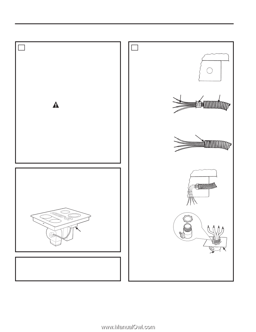
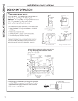
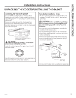
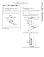
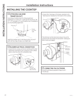
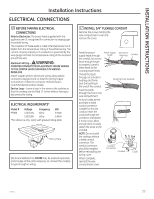
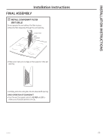
INSTALLATION INSTRUCTIONS Installation Instructions ELECTRICAL CONNECTIONS 16 BEFORE MAKING ELECTRICAL CONNECTIONS Note to Electrician: The power leads supplied with this appliance are UL-recognized for connection to large gauge household wiring. The insulation of these leads is rated at temperatures much higher than the temperature rating of household wiring. The current carrying capacity of a conductor is governed by the wire gauge and also the temperature rating of the insulation around the wire. Aluminum Wiring - WARNING: IMPROPER CONNECTION OF ALUMINUM HOUSE WIRING TO THE COPPER LEADS CAN RESULT IN SERIOUS PROBLEMS. Attach copper wires to aluminum wiring using special connectors designed and UL-listed for joining copper to aluminum. Follow the connector manufacturer's recommended procedure closely. Service Loop - Leave a loop in the wires to the cooktop so that the cooktop can be lifted 12 inches without having to disconnect the wiring. ELECTRICAL REQUIREMENTS* Model # Voltage Frequency KW PP989 120/240V 60Hz 9.1KW 120/208V 60Hz 6.9KW *For reference only. Verify with product rating plate. Rating Plate Electrical installation kit JXCK89 may be ordered separately and includes all the parts necessary to connect the cooktop to typical rough-in wiring. 17 INSTALL 3/4" FLEXIBLE CONDUIT Remove the screws holding the wire compartment cover and remove the cover. Feed the power supply leads through the conduit; be sure to leave enough length to properly connect these leads to the cooktop power leads. Thread the leads through an anti-short bushing and firmly seat the bushing in the end of the conduit. Feed the leads through the hole in the wire compartment. As local codes permit purchase a listed conduit connector suitable for the size conduit. Insert the conduit through the connector and attach it to the cover. Allow enough slack to easily attach the wires to the cooktop. NOTE: Do not install the cooktop without a listed conduit connector. The conduit connector should be installed before reinstalling the wiring cover. When complete, reinstall the wire compartment cover. Power Supply Anti-Short Leads Bushing Conduit Bushing (Fully Seated) Conduit Connector Conduit Cover 49-80635-1 23
-
 1
1 -
2
-
3
-
4
-
5
-
6
-
7
-
8
-
9
-
10
-
11
-
12
-
13
-
14
-
15
-
16
-
17
-
 18
18 -
 19
19 -
 20
20 -
 21
21 -
 22
22 -
 23
23 -
 24
24 -
 25
25 -
 26
26 -
 27
27 -
 28
28 -
29
-
30
-
31
-
32
-
33
-
34
-
35
-
36
-
37
-
38
-
39
-
40
-
41
-
42
-
43
-
44
-
45
-
46
-
47
-
48
-
49
-
50
-
51
-
52
-
53
-
54
-
55
-
56
 |
 |