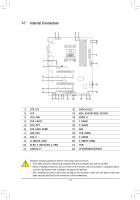
Gigabyte B450 AORUS PRO WIFI User Manual - Page 15
SYS_FAN3_PUMP System Fan/Water Cooling Pump Header, CPU_OPT Water Cooling CPU Fan Header - rgb header
 |
View all Gigabyte B450 AORUS PRO WIFI manuals
Add to My Manuals
Save this manual to your list of manuals |
Page 15 highlights
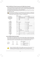
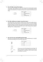
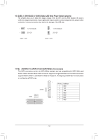
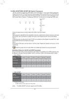
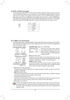
5) CPU_OPT (Water Cooling CPU Fan Header) The fan header is 4-pin and possesses a foolproof insertion design. Most fan headers possess a foolproof insertion design. When connecting a fan cable, be sure to connect it in the correct orientation (the black connector wire is the ground wire). The speed control function requires the use of a fan with fan speed control design. Pin No. Definition 1 GND 1 2 Voltage Speed Control 3 Sense 4 PWM Speed Control 6) SYS_FAN3_PUMP (System Fan/Water Cooling Pump Header) The fan/pump header is 4-pin and possess a foolproof insertion design. Most fan headers possess a foolproof insertion design. When connecting a fan cable, be sure to connect it in the correct orientation (the black connector wire is the ground wire). The speed control function requires the use of a fan with fan speed control design. For optimum heat dissipation, it is recommended that a system fan be installed inside the chassis. The header also provides speed control for a water cooling pump, refer to Chapter 2, "BIOS Setup," "M.I.T.," for more information. Pin No. Definition 1 GND 1 2 Voltage Speed Control 3 Sense 4 PWM Speed Control 7) LED_CPU (CPU Cooler LED Strip/RGB LED Strip Header) The header can be used to connect a CPU cooler LED strip or a standard 5050 RGB LED strip (12V/G/R/B), with maximum power rating of 2A (12V) and maximum length of 2m. Pin No. Definition 1 12V 1 2G 3R 4B LED Strip 1 12V Connect the CPU cooler LED strip/RGB LED strip to the header. The power pin (marked with a triangle on the plug) of the LED strip must be connected to Pin 1 of this header. Incorrect connection may lead to the damage of the LED strip. - 15 -
-
 1
1 -
2
-
3
-
4
-
5
-
6
-
7
-
8
-
9
-
 10
10 -
 11
11 -
 12
12 -
 13
13 -
 14
14 -
 15
15 -
 16
16 -
 17
17 -
 18
18 -
 19
19 -
 20
20 -
21
-
22
-
23
-
24
-
25
-
26
-
27
-
28
-
29
-
30
-
31
-
32
-
33
-
34
-
35
-
36
-
37
-
38
-
39
-
40
-
41
-
42
-
43
-
44
-
45
-
46
-
47
-
48
 |
 |
