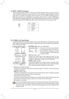
Gigabyte B450 AORUS PRO WIFI User Manual - Page 17
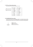
ASATA3 0/1, SATA3 0/1/2/3 SATA 6Gb/s Connectors
 |
View all Gigabyte B450 AORUS PRO WIFI manuals
Add to My Manuals
Save this manual to your list of manuals |
Page 17 highlights
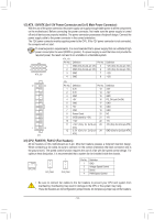
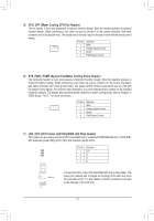
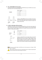
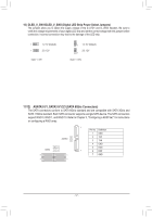
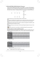
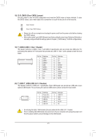
10) DLED_V_SW1/DLED_V_SW2 (Digital LED Strip Power Select Jumpers) The jumpers allow you to select the supply voltage of the D_LED1 and D_LED2 headers. Be sure to verify the voltage requirements of your digital LED strip and set the correct voltage with this jumper before connection. Incorrect connection may lead to the damage of the LED strip. 1 1-2: 5V (Default) 1 2-3: 12V DLED_V_SW1 1 1-2: 5V (Default) 2-3: 12V 1 DLED_V_SW2 11/12) ASATA3 0/1, SATA3 0/1/2/3 (SATA 6Gb/s Connectors) The SATA connectors conform to SATA 6Gb/s standard and are compatible with SATA 3Gb/s and SATA 1.5Gb/s standard. Each SATA connector supports a single SATA device. The SATA connectors support RAID 0, RAID 1, and RAID 10. Refer to Chapter 3, "Configuring a RAID Set," for instructions on configuring a RAID array. 1 SATA3 ASATA3 G.QBOFM 02 13 0 1 G.QBOFM 7 7 1 7 1 Pin No. 1 2 3 4 5 6 7 Definition GND TXP TXN GND RXN RXP GND DEBUG PORT DEBUG PORT - 17 -
-
 1
1 -
2
-
3
-
4
-
5
-
6
-
7
-
8
-
9
-
10
-
11
-
 12
12 -
 13
13 -
 14
14 -
 15
15 -
 16
16 -
 17
17 -
 18
18 -
 19
19 -
 20
20 -
 21
21 -
 22
22 -
23
-
24
-
25
-
26
-
27
-
28
-
29
-
30
-
31
-
32
-
33
-
34
-
35
-
36
-
37
-
38
-
39
-
40
-
41
-
42
-
43
-
44
-
45
-
46
-
47
-
48
 |
 |
