Gigabyte B450 AORUS PRO WIFI User Manual - Page 19
SPDIF_O S/PDIF Out Header, F_PANEL Front Panel Header, SPEAK, PLED/PWR_LED
 |
View all Gigabyte B450 AORUS PRO WIFI manuals
Add to My Manuals
Save this manual to your list of manuals |
Page 19 highlights
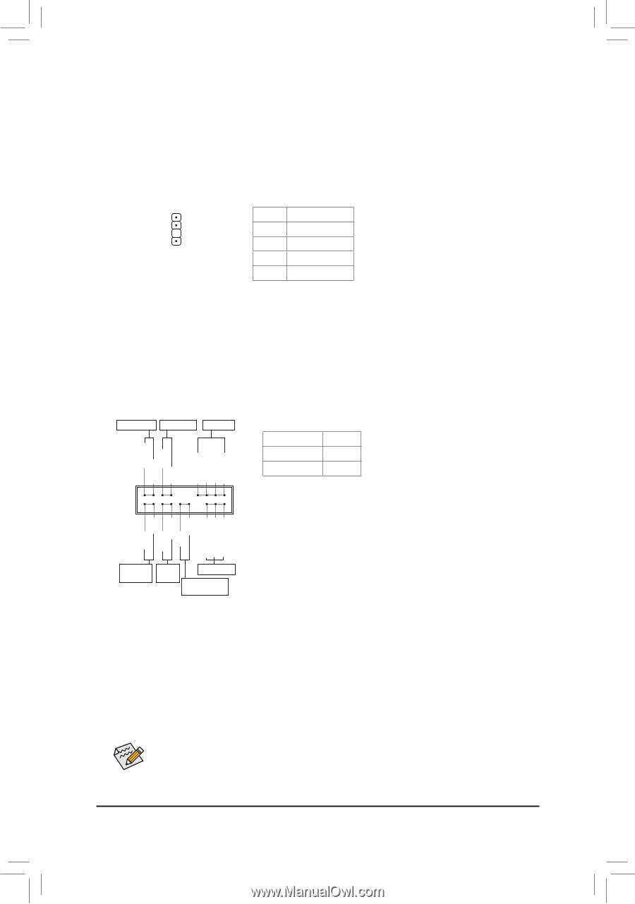
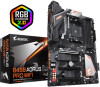
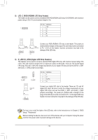
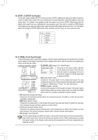
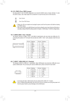
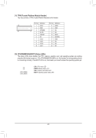
_ _B _ _F 14) SPDIF_O (S/PDIF Out Header) This header supports digital S/PDIF Out and connects a S/PDIF digital audio cable (provided by expansion cards) sound for digital audio output from your motherboard cards. For example, some graphics cards may troeqcueirrteaiyno_eu0xtpoaunFsseiona cards like graphics cards and S/PDIF digital audio cable for digital audio output from your motherboard to your graphics card if you wish to connect an HDMI display to the graphics card and have digital audio output from the HDMI display at the same time. For information about connecting the S/PDIF digital audio cable, carefully read the manual for your expansion card. Pin No. Definition S F_ 1 5VDUAL 2 No Pin 1 3 SPDIFO 4 GND F_USB3 _3 U 15) F_PANEL (Front Panel Header) Connect the power switch, reset switch, speaker, chassis intrusion switch/sensor and system status indicator on the chassis to this header according to the pin assignments below. Note the positive and negative pins before connecting the cables. Power LED Power Switch Speaker •• PLED/PWR_LED (Power LED, Yellow/Purple): System Status LED Connects to the power status indicator PLED+ PLED- PW+ PWSPEAK+ NC NC SPEAK- S0 On S3/S4/S5 Off on the chassis front panel. The LED is on when the system is operating. The LED is off when the system is in S3/S4 sleep state 2 1 20 19 •• or powered off (S5). PW (Power Switch, Red): Connects to the power switch on the chassis front panel. You may HD+ HD- RESRES+ CICI+ PWR_LED+ PWR_LEDPWR_LED- configure the way to turn off your system using the power switch (refer to Chapter 2, "BIOS Setup," "Power," for more information). •• SPEAK (Speaker, Orange): Hard Drive Reset Activity LED Switch Power LED Chassis Intrusion Header Connects to the speaker on the chassis front panel. The system reports system startup status by issuing a beep code. One single short beep will be heard if no problem is detected at system startup. •• HD (Hard Drive Activity LED, Blue): Connects to the hard drive activity LED on the chassis front panel. The LED is on when the hard drive is reading or writing data. •• RES (Reset Switch, Green): Connects to the reset switch on the chassis front panel. Press the reset switch to restart the computer if the computer freezes and fails to perform a normal restart. •• CI (Chassis Intrusion Header, Gray): Connects to the chassis intrusion switch/sensor on the chassis that can detect if the chassis cover has been removed. This function requires a chassis with a chassis intrusion switch/sensor. •• NC (Orange): No Connection. The front panel design may differ by chassis. A front panel module mainly consists of power switch, reset switch, power LED, hard drive activity LED, speaker and etc. When connecting your chassis front panel module to this header, make sure the wire assignments and the pin assignments are matched correctly. - 19 -
-
 1
1 -
2
-
3
-
4
-
5
-
6
-
7
-
8
-
9
-
10
-
11
-
12
-
13
-
 14
14 -
 15
15 -
 16
16 -
 17
17 -
 18
18 -
 19
19 -
 20
20 -
 21
21 -
 22
22 -
 23
23 -
 24
24 -
25
-
26
-
27
-
28
-
29
-
30
-
31
-
32
-
33
-
34
-
35
-
36
-
37
-
38
-
39
-
40
-
41
-
42
-
43
-
44
-
45
-
46
-
47
-
48
 |
 |