Gigabyte B450 AORUS PRO WIFI User Manual - Page 21
F_USB1/F_USB2 USB 2.0/1.1 Headers, F_USB30 USB 3.1 Gen 1 Header, CLR_CMOS Clear CMOS Jumper
 |
View all Gigabyte B450 AORUS PRO WIFI manuals
Add to My Manuals
Save this manual to your list of manuals |
Page 21 highlights
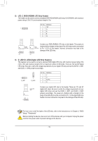
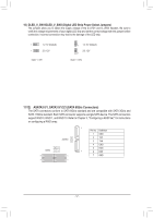
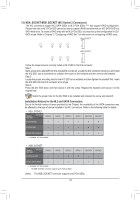
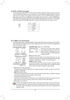
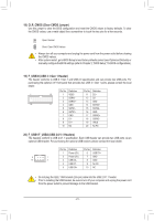
18) CLR_CMOS (Clear CMOS Jumper) Use this jumper to clear the BIOS configuration and reset the CMOS values to factory defaults. To clear the CMOS values, use a metal object like a screwdriver to touch the two pins for a few seconds. Open: Normal Short: Clear CMOS Values •• Always turn off your computer and unplug the power cord from the power outlet before clearing the CMOS values. •• After system restart, go to BIOS Setup to load factory defaults (select Load Optimized Defaults) or manually configure the BIOS settings (refer to Chapter 2, "BIOS Setup," for BIOS configurations). 19) F_USB30 (USB 3.1 Gen 1 Header) The header conforms to UGS.BQB3O.F1MGen 1 and USB 2.0 specification and can provide two USB ports. For purchasing the optional 3.5" front panel that provides two USB 3.1 Gen 1 ports, please contact the local dealer. 1 F_USB30 20 Pin No. Definition Pin No. Definition 10 1 VBUS 11 D2+ F2_ U SSRX1- 12 D2- F_ 3 SSRX1+ 13 GND 11 4 GND 14 SSTX2+ 5 SSTX1- 15 SSTX2- 6 SSTX1+ 16 GND 7 GND 17 SSRX2+ 8 D1- 18 SSRX2- 9 D1+ 19 VBUS 10 NC 20 No Pin B SS 20) F_USB1/F_USB2 (USB 2.0/1.1B_Headers) The headers conform to USB 2.0/1.1 specification. Each USB header can1 provide two USB ports via an optional USB bracket. For purchasing the optional USB bracket, please contact the local dea_leSr. 1 23 1 1 23 1 1 23 1 Pin No. Definition Pin No. Definition 1 Power (5V) 6 USB DY+ 9 1 10 2 2 Power (5V) 3 USB DX- 7 GND S 8 GND 4 USB DY- 9 No Pin 5 USB DX+ 10 NC 1 23 S •• Do not plug the IEEE 1394 bracket (2x5-pin) cable into the USB 2.0/1.1 header. •• Prior to installing the USB bracket, be sure to turn off your computer and unplug the power cord from the power outlet to prevent damage to the USB bracket. S3 - 21 - B SS S U __ 3
-
 1
1 -
2
-
3
-
4
-
5
-
6
-
7
-
8
-
9
-
10
-
11
-
12
-
13
-
14
-
15
-
 16
16 -
 17
17 -
 18
18 -
 19
19 -
 20
20 -
 21
21 -
 22
22 -
 23
23 -
 24
24 -
 25
25 -
 26
26 -
27
-
28
-
29
-
30
-
31
-
32
-
33
-
34
-
35
-
36
-
37
-
38
-
39
-
40
-
41
-
42
-
43
-
44
-
45
-
46
-
47
-
48
 |
 |