Gigabyte C7V7-CSI Manual - Page 12
Power Connector 2x10 pin ATX
 |
View all Gigabyte C7V7-CSI manuals
Add to My Manuals
Save this manual to your list of manuals |
Page 12 highlights
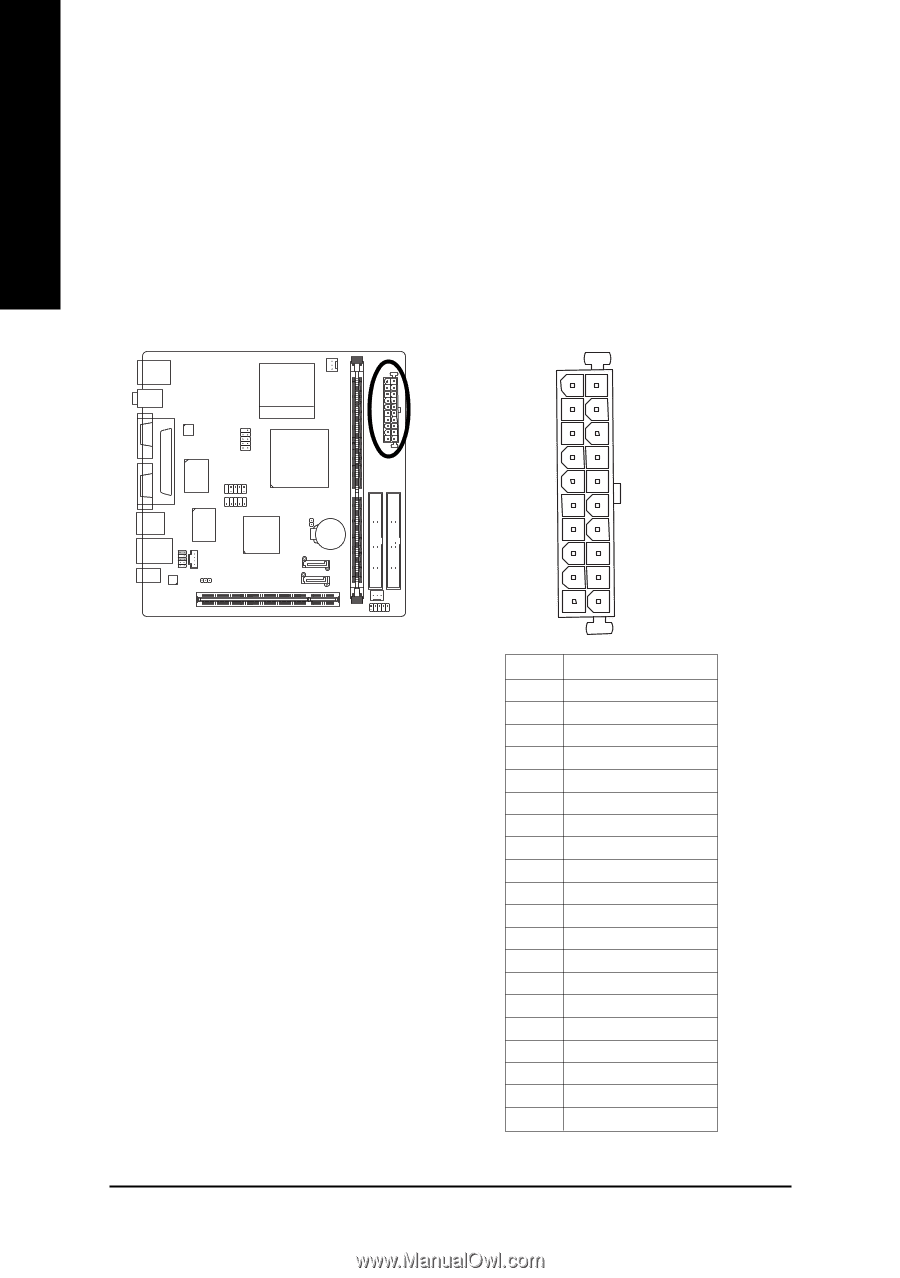
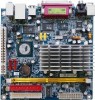
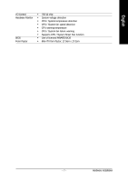
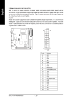
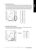
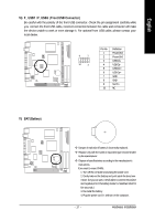
English 1) Power Connector (2x10 pin ATX ) With the use of the power connector, the power supply can supply enough stable power to all the components on the motherboard. Before connecting the power connector, please make sure that all components and devices are properly installed. Align the power connector with its proper location on the motherboard and connect it tightly. Caution! Please use a power supply that is able to handle the system voltage requirements. It is recommended that a power supply that can withstand high power consumption be used (300W or greater). If a power supply is used that does not provide the required power, the result can lead to an unstable system or a system that is unable to start. 10 20 GA-C7V7-RH Motherboard 1 11 Pin No. 1 2 3 4 5 6 7 8 9 10 11 12 13 14 15 16 17 18 19 20 Definition 3.3V 3.3V GND +5V GND +5V GND Power Good 5V SB (stand by +5V) +12V 3.3V -12V GND PS_ON(soft on/off) GND GND GND -5V +5V +5V - 12 -
-
 1
1 -
2
-
3
-
4
-
5
-
6
-
 7
7 -
 8
8 -
 9
9 -
 10
10 -
 11
11 -
 12
12 -
 13
13 -
 14
14 -
 15
15 -
 16
16 -
 17
17 -
18
-
19
-
20
-
21
-
22
-
23
-
24
-
25
-
26
-
27
-
28
-
29
-
30
-
31
-
32
-
33
-
34
-
35
-
36
-
37
-
38
-
39
-
40
-
41
-
42
-
43
-
44
-
45
-
46
-
47
-
48
 |
 |