Gigabyte G1.Sniper 3 Manual - Page 11
Support for RAID 0, RAID 1, RAID 5, and RAID 10 - bios
 |
View all Gigabyte G1.Sniper 3 manuals
Add to My Manuals
Save this manual to your list of manuals |
Page 11 highlights
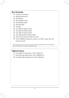
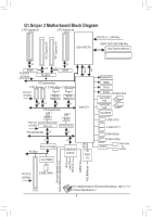
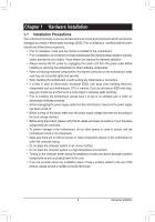
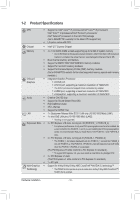
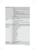
Storage Interface Š Š USB Š Š IEEE 1394 Š Internal Š Connectors Š Š Š Š Š Š Š Š Š Š Š Š Š Š Š Š Š Š Š Back Panel Š Connectors Š Š Chipset: - 2 x SATA 6Gb/s connectors (SATA3 0/1) supporting up to 2 SATA 6Gb/s devices - 4 x SATA 3Gb/s connectors (SATA2 2/3/4/5) supporting up to 4 SATA 3Gb/s devices - 1 x mSATA connector * The SATA2 5 connector will become unavailable when the mSATA connector is installed with a solid state drive. - Support for RAID 0, RAID 1, RAID 5, and RAID 10 * When a RAID set is built across the SATA 6Gb/s and SATA 3Gb/s channels, the system performance of the RAID set may vary depending on the devices being connected. 2 x Marvell 88SE9172 chips: - 4 x SATA 6Gb/s connectors (GSATA3 6/7/8/9) supporting up to 4 SATA 6Gb/s devices - Support for RAID 0 and RAID 1 Chipset: - Up to 2 USB 3.0/2.0 ports on the back panel - Up to 4 USB 2.0/1.1 ports (available through the internal USB headers) Chipset + 2 VIA VL810 Hubs: - Up to 8 USB 3.0/2.0 ports (4 ports on the back panel, 4 ports available through the internal USB headers) VIA VT6308 chip: - Up to 2 IEEE 1394a ports (available through the internal IEEE 1394a headers) 1 x 24-pin ATX main power connector 1 x 8-pin ATX 12V power connector 1 x PCIe power connector 6 x SATA 6Gb/s connectors 4 x SATA 3Gb/s connectors 1 x mSATA connector 1 x CPU fan header 4 x system fan headers 1 x front panel header 1 x front panel audio header 2 x USB 2.0/1.1 headers 2 x USB 3.0/2.0 headers 2 x IEEE 1394a headers 1 x Clear CMOS jumper 1 x power button 1 x Clear CMOS button 1 x reset button Voltage measurement points 1 x BIOS switch 1 x Trusted Platform Module (TPM) header 1 x PS/2 keyboard/mouse port 6 x USB 3.0/2.0 ports 1 x D-Sub port - 11 - Hardware Installation
-
 1
1 -
2
-
3
-
4
-
5
-
 6
6 -
 7
7 -
 8
8 -
 9
9 -
 10
10 -
 11
11 -
 12
12 -
 13
13 -
 14
14 -
 15
15 -
 16
16 -
17
-
18
-
19
-
20
-
21
-
22
-
23
-
24
-
25
-
26
-
27
-
28
-
29
-
30
-
31
-
32
-
33
-
34
-
35
-
36
-
37
-
38
-
39
-
40
-
41
-
42
-
43
-
44
-
45
-
46
-
47
-
48
-
49
-
50
-
51
-
52
-
53
-
54
-
55
-
56
-
57
-
58
-
59
-
60
-
61
-
62
-
63
-
64
-
65
-
66
-
67
-
68
-
69
-
70
-
71
-
72
-
73
-
74
-
75
-
76
-
77
-
78
-
79
-
80
-
81
-
82
-
83
-
84
-
85
-
86
-
87
-
88
-
89
-
90
-
91
-
92
-
93
-
94
-
95
-
96
-
97
-
98
-
99
-
100
-
101
-
102
-
103
-
104
-
105
-
106
-
107
-
108
-
109
-
110
-
111
-
112
-
113
-
114
-
115
-
116
-
117
-
118
-
119
-
120
-
121
-
122
-
123
-
124
-
125
-
126
-
127
-
128
 |
 |
