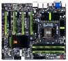
Gigabyte G1.Sniper 3 Manual - Page 33
F_AUDIO Front Panel Audio Header, CLR_CMOS Clear CMOS Jumper - sata setup
 |
View all Gigabyte G1.Sniper 3 manuals
Add to My Manuals
Save this manual to your list of manuals |
Page 33 highlights
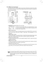
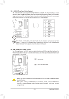
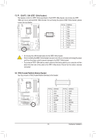
13) F_AUDIO (Front Panel Audio Header) The front panel audio header supports Intel High Definition audio (HD). You may connect your chassis front panel audio module to this header. Make sure the wire assignments of the module connector match the pin assignments of the motherboard header. Incorrect connection between the module connector and the motherboard header will make the device unable to work or even damage it. Pin No. Definition 1 MIC2_L 9 1 2 GND 30 F_AUDIO(H) F_PANEL3(NH) MIC2_R 10 2 4 -ACZ_DET 5 LINE2_R 6 GND 7 FAUDIO_JD 8 No Pin 9 LINE2_L 10 GND SomDeB_cPhOaRsTsis provide a front panel BIOS Switcher (X58A-OC) audio module that has separated connectors on each wire instead of a single plug. For information ab1out connecting the front panel audio module that has different wire assignments, please contact the chassis manufaMc_tSuArTeAr. DIP 1 23 1 DIP 1 23 1 DIP 1 23 1 14) CLR_CVMolOtagSe m(Cealseuraemr eCntMmoOduSle(JX5u8mA-OpCe)r) ng Use this jumper to clear the CMOS values (e.gP. WdaMteSwiintcfho(rXm58aAti-oOnC)and BIOS configurations) and reset the CMOS values to factory defaults. To clear the CMOS values, use a metal object like a screwdriver to touch the two pins for a few seconds. DIP 1 23 PCIe power connector (SATA)(X58A-OC) Open: Normal Short: Clear CMOS Values Voltage measurement points(G1.Sniper 3) BIOS Switcher (SW4) •• Always turn off your computer and unplug the power cord from the power outlet before clearing the CMOS values. •• After system restart, go to BIOS Setup to load factory defaults (select Load Optimized Defaults) or manually configure the BIOS settings (refer to Chapter 2, "BIOS Setup," for BIOS configurations). - 33 - Hardware Installation F_PANEL (H61M-D2) ACPI_CPT (GA-IVB) SMB_CPT (GA-IVB) CLR_CMOS CI DIS_ME GP15_CPT (GA-IVB) XDP_CPU XDP_PCH (GA-IVB)
-
 1
1 -
2
-
3
-
4
-
5
-
6
-
7
-
8
-
9
-
10
-
11
-
12
-
13
-
14
-
15
-
16
-
17
-
18
-
19
-
20
-
21
-
22
-
23
-
24
-
25
-
26
-
27
-
 28
28 -
 29
29 -
 30
30 -
 31
31 -
 32
32 -
 33
33 -
 34
34 -
 35
35 -
 36
36 -
 37
37 -
 38
38 -
39
-
40
-
41
-
42
-
43
-
44
-
45
-
46
-
47
-
48
-
49
-
50
-
51
-
52
-
53
-
54
-
55
-
56
-
57
-
58
-
59
-
60
-
61
-
62
-
63
-
64
-
65
-
66
-
67
-
68
-
69
-
70
-
71
-
72
-
73
-
74
-
75
-
76
-
77
-
78
-
79
-
80
-
81
-
82
-
83
-
84
-
85
-
86
-
87
-
88
-
89
-
90
-
91
-
92
-
93
-
94
-
95
-
96
-
97
-
98
-
99
-
100
-
101
-
102
-
103
-
104
-
105
-
106
-
107
-
108
-
109
-
110
-
111
-
112
-
113
-
114
-
115
-
116
-
117
-
118
-
119
-
120
-
121
-
122
-
123
-
124
-
125
-
126
-
127
-
128
 |
 |
