Gigabyte G1.Sniper 5 User Manual - Page 22
Onboard Buttons, Switches and LEDs, Quick Buttons, BIOS Switch and BIOS LED Indicators
 |
View all Gigabyte G1.Sniper 5 manuals
Add to My Manuals
Save this manual to your list of manuals |
Page 22 highlights
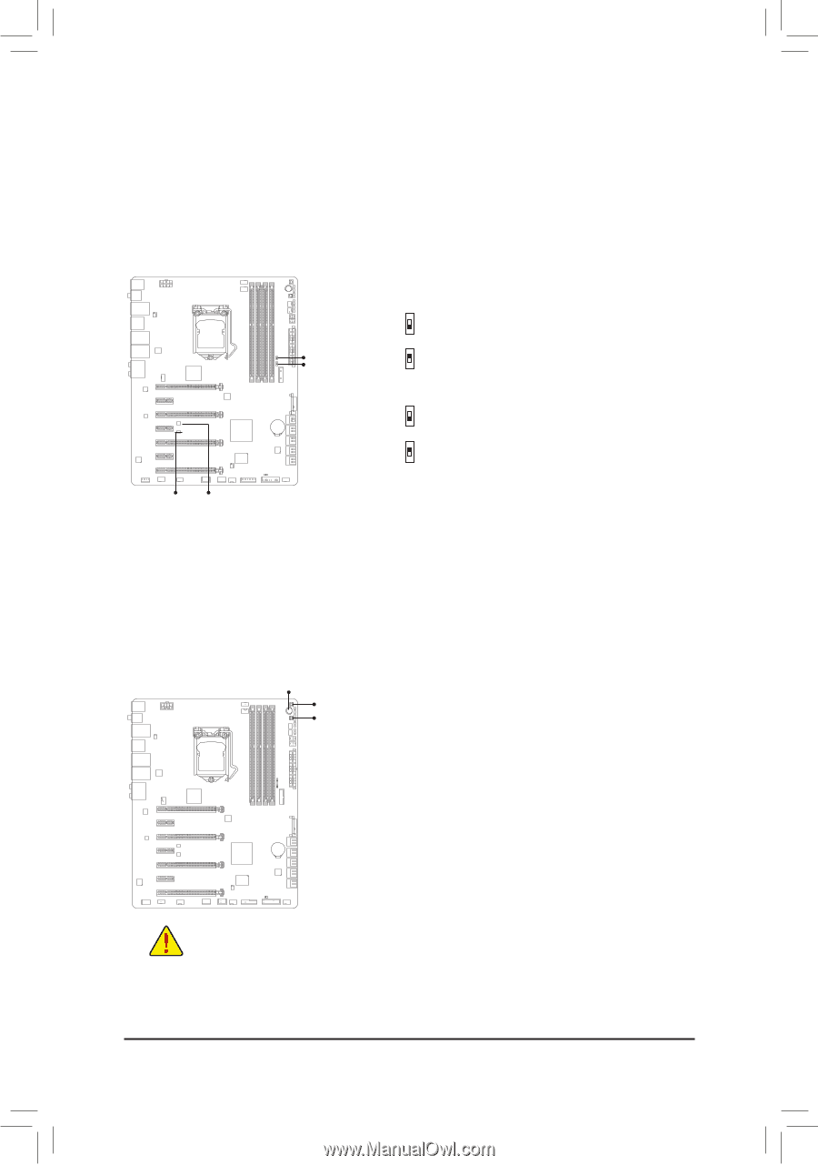
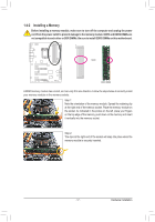
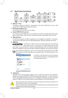
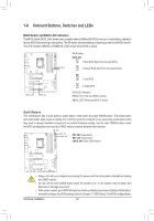
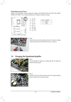
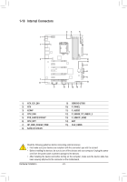
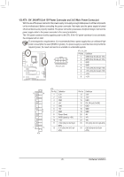
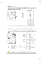
ATX_12V_2X3 ATX_12V_2X3 1-8 Onboard Buttons, Switches and LEDs BIOS Switch and BIOS LED Indicators The BIOS switch (BIOS_SW) allows users to easily select a different BIOS for boot up or overclocking, helping to reduce BIOS failure during overclocking. The SB switch allows enabling of disabling or the Dual BIOS function. The LED indicator (MBIOS_LED/BBIOS_LED) shows which BIOS is active. Voltage measurement points(G1.Sniper 3) Voltage measurement points(G1.Sniper 3) DDIIPP 11 22 33 44 DDIIPP 11 22 33 44 DIP 1 234 DIP 1 234 MBIOS_LED BBIOS_LED PCIe Control (Z87X-UP7) DIP 1 234 PCIe Control (Z87X-UP7) DDIIPP 11 22 33 44 DIP 1 234 DDIIPP 11 22 33 44 BIOS_SW SB BIOS Switcher (SW4) BIOS Switcher (SW4) BIOS Switch: BIOS_SW 2 1 1: Main BIOS (Boot from the main BIOS) 2 2: Backup BIOS (Boot from the backup BIOS) 1 SB 2 1: Dual BIOS 1 2 2: Single BIOS 1 BIOS LED Indicators: MBIOS_LED (The main BIOS is active) BBIOS_LED (The backup BIOS is active) DDIIPP 11 22 33 PCIe power connector (SATA)(X58A-OC) DDIIPP 11 22 33 DDIIPP 11 22 33 Quick Buttons This motherboard has 3 quick buttons: power button, reset button and clear CMOS button. The power button and reset button allowDDIIPP users to quickly turn on/off or reset the computer in an open-case environment when 11 22 33 they want to change hardware components or conduct hardware testing. Use the clear CMOS button to clear the BIOS configuration and reset the CMOS values to factory defaults when needed. Voltage measurement module(X58A-OC) PCIe power connector (SATA)(X58A-OC) DIP 1 23 PWM Switch (X58A-OC) DIP 1 23 PW_SW M_SATA DIP RST_SW CMOS_SW PW_SW: Power button 11 1 23 1 23 11 DIP RST_SW: Reset button CMOS_SW: Clear CMOS Button PW 11M Switch (X58A-OC) VoltaDgBe_PmOeaRsTurement module(X58A-OC) 11 BIOS Switcher (X58A-OC) 1 1 F_USB30 TPM w/housing TPM w/housing BIOS Switcher (X58A-OC) 1 M_SATA 1 DB_PORT F_AUDIO(H) F_PANEL(NH) •• Always turn off your computer and unplug the power cord from the power outlet before clearing the CMOS values. •• Do not use the clear CMOS button when the system is on, or the system may shutdown and data loss or damage may occur. •• After system restart, go to BIOS Setup to load factory defaults (select Load Optimized Defaults) or manually configure the BIOS settings (refer to Chapter 2, "BIOS Setup," for BIOS configurations). F_AUDIO(H) F_PANEL(NH) Hardware Installation - 22 - F_USB30
-
 1
1 -
2
-
3
-
4
-
5
-
6
-
7
-
8
-
9
-
10
-
11
-
12
-
13
-
14
-
15
-
16
-
 17
17 -
 18
18 -
 19
19 -
 20
20 -
 21
21 -
 22
22 -
 23
23 -
 24
24 -
 25
25 -
 26
26 -
 27
27 -
28
-
29
-
30
-
31
-
32
-
33
-
34
-
35
-
36
-
37
-
38
-
39
-
40
-
41
-
42
-
43
-
44
-
45
-
46
-
47
-
48
-
49
-
50
-
51
-
52
-
53
-
54
-
55
-
56
-
57
-
58
-
59
-
60
-
61
-
62
-
63
-
64
-
65
-
66
-
67
-
68
-
69
-
70
-
71
-
72
-
73
-
74
-
75
-
76
-
77
-
78
-
79
-
80
-
81
-
82
-
83
-
84
-
85
-
86
-
87
-
88
-
89
-
90
-
91
-
92
-
93
-
94
-
95
-
96
-
97
-
98
-
99
-
100
-
101
-
102
-
103
-
104
-
105
-
106
-
107
-
108
-
109
-
110
-
111
-
112
-
113
-
114
-
115
-
116
-
117
-
118
-
119
-
120
 |
 |