Gigabyte G1.Sniper 5 User Manual - Page 23
Changing the Operational Amplifier, Voltage Measurement Points
 |
View all Gigabyte G1.Sniper 5 manuals
Add to My Manuals
Save this manual to your list of manuals |
Page 23 highlights
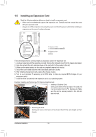
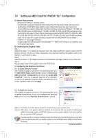
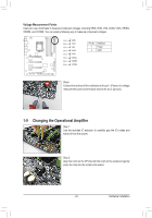
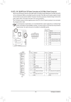
DIP 1 234 DIP 1 234 DIP 1 234 DIP 1 234 DIP 1 234 DIP 1 234 DIP 1 234 DIP 1 234 DIP 1 23 DIP 1 23 DIP 1 23 DIP 1 23 DIP 1 1 23 DIP 1 1 23 DIP 1 1 23 DIP 1 1 23 1 23 1 23 1 23 1 23 1 23 1 23 1 23 TPM w/housing TPM w/housing TPM w/housing TPM w/housing TPM w/housing TPM w/housing TPM w/housing Voltage Measurement Points VoltDagBe_PmOeRasTurement module(X58A-OC) VoltDagBe_PmOeRasTurement module(X58A-OC) Voltage measurement module(X58A-OC) PCIe power connector (SATA)(X58A-OC) Voltage measurement module(X58A-OC) PCIe power connector (SATA)(X58A-OC) Voltage measurement module(X58A-OC) PCIe power connector (SATA)(X58A-OC) Voltage measurement module(X58A-OC) PCIe power connector (SATA)(X58A-OC) PCIe power connector (SATA)(X58A-OC) DIP DIP DIP DIP DIP DIP DIP D 1 1 1 1 1 23 1 23 1 23 1 23 1 23 1 1 23 1 2 1 BIPOWSMS1 wSiwtcihtcehr (X58A-OC) BIPOWSMS1 wSDiwtIPcihtcehr (X58A-OC) PWM1 1S2DwI3Pitch (X58A-OC) 1 23 PWM SDwIPitch (X58A-OC) 1 23 PWM SDwIPitch (X58A-OC) 1 23 PWM SDwIPitch (X58A-OC) 1 23 PWM SDwIPitch (X58A-OC) 1 23 DIP DIP DIP DIP DIP DIP DIP M_SATA M_SATA M_SATA M_SATA 1 23 DIP Users can use a multimeter to measure component voltages, including PVCRIe pINow,erVcoInOneDcto,r (VSASTAA)(X,5V8AA-OXC)G, VIOA,1 2 3 DIP VRING, DIP VDIMM, and VCORE. You can employ following way to measure comPpCoIenpoewnertcovnonelcttaorg(SeATsA.)(X58A-OC) 1 23 PCIe power connector (SATA)(X58A-OC) Voltage measurement points(G1.Sniper 3) BIOS Switcher (SW4) Pin 1Voltage mVeRasIuNrement points(G1.Sniper 3) Pin 1Voltage mVeIaOsuDrement points(G1.Sniper 3P) in No. Pin 1Voltage mVeSasAurement points(G1.Sniper 3) 1 Pin 1Voltage mVeAasXuGrement points(G1.Sniper 3) 2 Pin 1Voltage mVeIaOsuArement points(G1.Sniper 3) Pin 1Voltage mVeRasIuNreGment points(G1.Sniper 3) Pin 1Voltage mVeDasIuMreMment points(G1.Sniper 3) BIOS Switcher (SW4) DBIeOSfinSwitiitcohner (SW4) PBIoOwS Sewritcher (SW4) GBIONSDSwitcher (SW4) BIOS Switcher (SW4) BIOS Switcher (SW4) BIOS Switcher (SW4) DIP DIP DIP DIP DIP DIP DIP PCIe Control (Z87X-UP7) PCIe Control (Z87X-UP7) PCIe Control (Z87X-UP7) DIP PCIe Control (Z87X-UP7) 1 234 DIP PCIe Control (Z87X-UP7) 1 234 DIP PCIe Control (Z87X-UP7) 1 234 DIP PCIe Control (Z87X-UP7) 1 234 DIP PCIe Control (Z87X-UP7) 1 234 DIP DIP DIP DIP DIP DIP DIP ATX_12V_2X3 ATX_12V_2X3 ATX_12V_2X3 ATX_12V_2X3 ATX_12V_2X3 ATX_12V_2X3 ATX_12V_2X3 ATX_12V_2X3 1 2 3 4 1 2 3 4 1 2 3 4 1 2 3 4 1 2 3 4 1 2 3 4 1 2 3 41 2 3 4 1 2 3 41 2 3 4 1 2 3 4 1 2 3 4 1 2 3 4 1 2 3 4 1 2 3 4 1 2 3 4 DIP DIP Pin 1 VCORE 1 234 DIP DIP 1 234 DIP 1 234 Steps: Connect the red lead of the multimeter to the pin 1 (Power) of a voltage measurement point and the black lead to the pin 2 (ground). 1-9 Changing the Operational Amplifier Step 1: Use the included IC extractor to carefully grip the IC's sides and extract it from the socket. Step 2: Align the notch on the OP chip with the notch on the socket and gently press the chip into the socket until seated. - 23 - Hardware Installation
-
 1
1 -
2
-
3
-
4
-
5
-
6
-
7
-
8
-
9
-
10
-
11
-
12
-
13
-
14
-
15
-
16
-
17
-
 18
18 -
 19
19 -
 20
20 -
 21
21 -
 22
22 -
 23
23 -
 24
24 -
 25
25 -
 26
26 -
 27
27 -
 28
28 -
29
-
30
-
31
-
32
-
33
-
34
-
35
-
36
-
37
-
38
-
39
-
40
-
41
-
42
-
43
-
44
-
45
-
46
-
47
-
48
-
49
-
50
-
51
-
52
-
53
-
54
-
55
-
56
-
57
-
58
-
59
-
60
-
61
-
62
-
63
-
64
-
65
-
66
-
67
-
68
-
69
-
70
-
71
-
72
-
73
-
74
-
75
-
76
-
77
-
78
-
79
-
80
-
81
-
82
-
83
-
84
-
85
-
86
-
87
-
88
-
89
-
90
-
91
-
92
-
93
-
94
-
95
-
96
-
97
-
98
-
99
-
100
-
101
-
102
-
103
-
104
-
105
-
106
-
107
-
108
-
109
-
110
-
111
-
112
-
113
-
114
-
115
-
116
-
117
-
118
-
119
-
120
 |
 |
