Gigabyte G210-H4G Manual - Page 26
System Appearance, 3-1 Front View, 3-2 Rear View, Rear View
 |
View all Gigabyte G210-H4G manuals
Add to My Manuals
Save this manual to your list of manuals |
Page 26 highlights
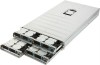
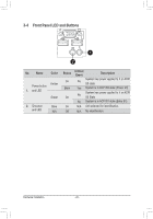
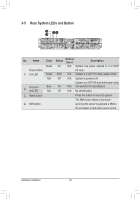
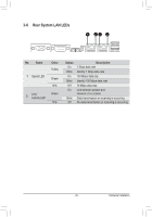
Chapter 3 System Appearance 3-1 Front View 3 1 42 5 5 3 1 42 3 12 4 No. Decription 1 ID button and LED 2. Power button and LED 3. VGA port 4. USB 3.0 ports 5. HDD bays 3 12 4 3-2 Rear View 1 2 3 46 5 7 8 9 2 13 46 5 7 8 2 1 35 78 46 2 13 5 78 46 No. Decription 1 VGA port 2. PCIe slot cover 3. Serial port 4. Power button and LED 5. ID Button and LED 6. Reset button (top)/NMI button (bottom) 7. LAN ports 8. USB 2.0 ports 9. Power module NOTE! For detail LED description, please see the following section: Front Panel LED and Buttons and Rear System LEDs and Button. - 26 - Hardware Installation
-
 1
1 -
2
-
3
-
4
-
5
-
6
-
7
-
8
-
9
-
10
-
11
-
12
-
13
-
14
-
15
-
16
-
17
-
18
-
19
-
20
-
 21
21 -
 22
22 -
 23
23 -
 24
24 -
 25
25 -
 26
26 -
 27
27 -
 28
28 -
 29
29 -
 30
30 -
 31
31 -
32
-
33
-
34
-
35
-
36
-
37
-
38
-
39
-
40
-
41
-
42
-
43
-
44
-
45
-
46
-
47
-
48
-
49
-
50
-
51
-
52
-
53
-
54
-
55
-
56
-
57
-
58
-
59
-
60
-
61
-
62
-
63
-
64
-
65
-
66
-
67
-
68
-
69
-
70
-
71
-
72
-
73
-
74
-
75
-
76
-
77
-
78
-
79
-
80
-
81
-
82
-
83
-
84
-
85
-
86
-
87
-
88
-
89
-
90
-
91
-
92
-
93
-
94
-
95
-
96
-
97
-
98
 |
 |

- 26 -
Hardware Installation
Chapter 3
System Appearance
3-1
Front View
No.
Decription
1
ID button and LED
2.
Power button and LED
3.
VGA port
4.
USB 3.0 ports
5.
HDD bays
3-2
Rear View
No.
Decription
1
VGA port
2.
PCIe slot cover
3.
Serial port
4.
Power button and LED
5.
ID Button and LED
6.
Reset button (top)/NMI button (bottom)
7.
LAN ports
8.
USB 2.0 ports
9.
Power module
1
1
3
4
5
9
6
6
3
2
2
7
8
7
8
4
5
1
1
3
4
5
6
6
3
2
2
7
8
7
8
4
5
NOTE!
For detail LED description, please see the following section:
Front Panel LED and Buttons
and
Rear System LEDs and Button
.
1
2
3
4
4
5
5
2
1
3
1
2
3
4
4
2
1
3