Gigabyte GA-6PXSVL Manual - Page 17
Back Panel Connectors
 |
View all Gigabyte GA-6PXSVL manuals
Add to My Manuals
Save this manual to your list of manuals |
Page 17 highlights
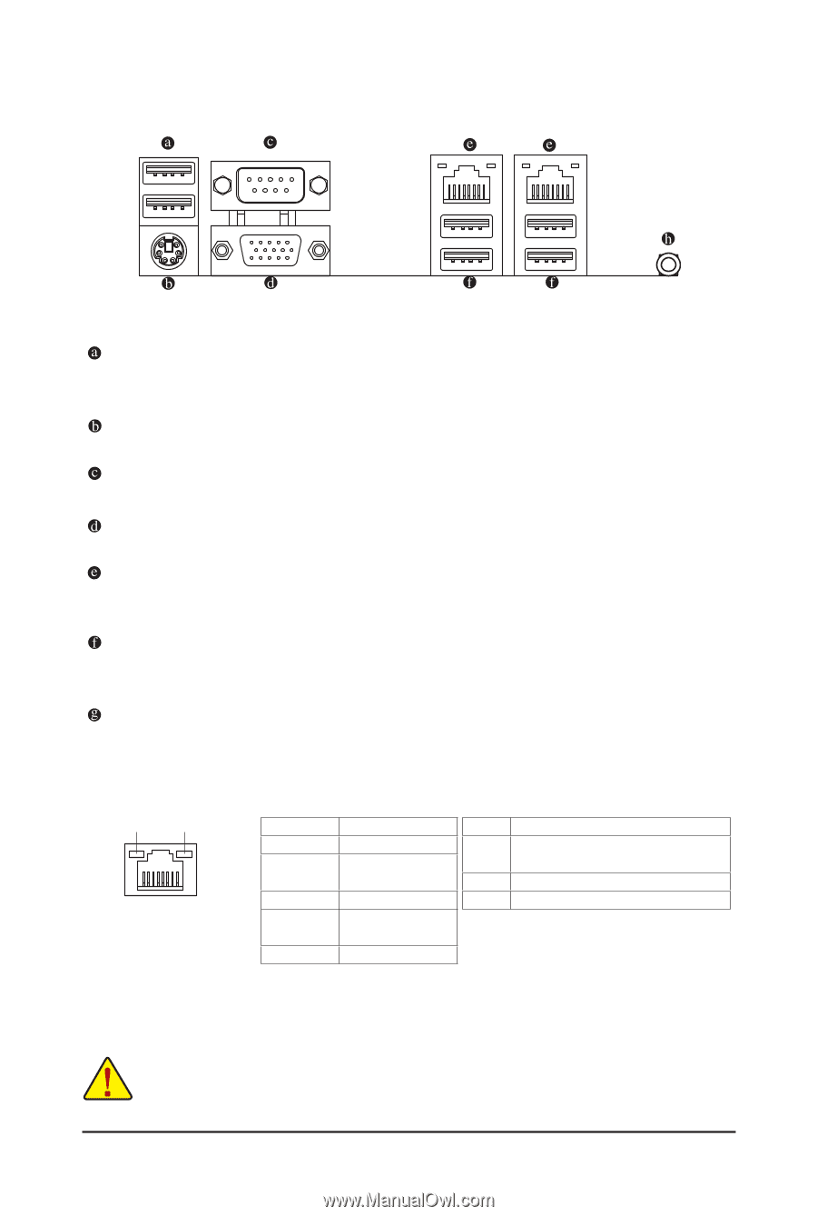
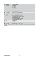
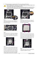
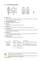
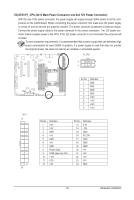
1-5 Back Panel Connectors USB 2.0 Port The USB port supports the USB 2.0 specification. Use this port for USB devices such as a USB keyboard/mouse, USB printer, USB flash drive and etc. PS/2 Keyboard/Mouse Port Coonnect a PS/2 keyboard or mouse to this port. Serial Port Connects to serial-based mouse or data processing devices. Video Port The video in port allows connect to video in, which can also apply to video loop thru function. RJ-45 LAN Port The Gigabit Ethernet LAN port provides Internet connection at up to 1 Gbps data rate. The following describes the states of the LAN port LEDs. USB 3.0 Port The USB port supports the USB 3.0 specification. Use this port for USB devices such as a USB keyboard/mouse, USB printer, USB flash drive and etc. ID Switch Button This button provide the selected unit idenfication function. Speed LED Link Activity LED 10/100/1000 LAN Port 82574 Speed LED: State Yellow On Yellow Blink Description 1 Gbps data rate Identify 1 Gbps data rate Green On Green Blink 100 Mbps data rate Identify 100 Mbps data rate Off 10 Mbps data rate Link/Activity LED: State Description On Link between system and network or no access Blinking Data transmission or receiving is occurring Off No data transmission or receiving is occurring • When removing the cable connected to a back panel connector, first remove the cable from your device and then remove it from the motherboard. • When removing the cable, pull it straight out from the connector. Do not rock it side to side to prevent an electrical short inside the cable connector. Hardware Installation - 17 -
-
 1
1 -
2
-
3
-
4
-
5
-
6
-
7
-
8
-
9
-
10
-
11
-
 12
12 -
 13
13 -
 14
14 -
 15
15 -
 16
16 -
 17
17 -
 18
18 -
 19
19 -
 20
20 -
 21
21 -
 22
22 -
23
-
24
-
25
-
26
-
27
-
28
-
29
-
30
-
31
-
32
-
33
-
34
-
35
-
36
-
37
-
38
-
39
-
40
-
41
-
42
-
43
-
44
-
45
-
46
-
47
-
48
-
49
-
50
-
51
-
52
-
53
-
54
-
55
-
56
-
57
-
58
-
59
-
60
-
61
-
62
-
63
-
64
-
65
-
66
-
67
-
68
-
69
-
70
-
71
-
72
-
73
-
74
-
75
-
76
-
77
-
78
-
79
-
80
-
81
-
82
 |
 |