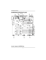
Gigabyte GA-8IPXDR-E User Manual - Page 10
Step 1: Install the Central Processing Unit CPU
 |
View all Gigabyte GA-8IPXDR-E manuals
Add to My Manuals
Save this manual to your list of manuals |
Page 10 highlights
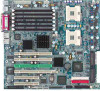
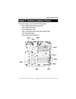
GA-8IPXDR-E(C) Motherboard Step 1: Install the Central Processing Unit (CPU) Step 1-1: Installing Motherboard to the Chassis... You may use the 4 screws which come with the mainboard to reinforce the support between Xeon CPU heat-sink on the mainboard and chassis. Step1: The 4 new mounting holes on the chassis are for additional support for Xeon CPU heat-sink on the mainboard. Step2: Preparing the assemblt kits. Step3: Fit the 4 screws with 2 CPU retention modules on the chassis. Figure 1 Figure 2 10
-
 1
1 -
2
-
3
-
4
-
 5
5 -
 6
6 -
 7
7 -
 8
8 -
 9
9 -
 10
10 -
 11
11 -
 12
12 -
 13
13 -
 14
14 -
 15
15 -
16
-
17
-
18
-
19
-
20
-
21
-
22
-
23
-
24
-
25
-
26
-
27
-
28
-
29
-
30
-
31
-
32
-
33
-
34
-
35
-
36
-
37
-
38
-
39
-
40
-
41
-
42
-
43
-
44
-
45
-
46
-
47
-
48
-
49
-
50
-
51
-
52
-
53
-
54
-
55
-
56
-
57
-
58
-
59
-
60
-
61
-
62
-
63
-
64
-
65
-
66
-
67
-
68
-
69
-
70
 |
 |
10
GA-8IPXDR-E(C) Motherboard
Step 1: Install the Central Processing Unit (CPU)
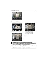
Step 1-1: Installing Motherboard to the Chassis...
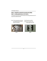
You may use the 4 screws which come with the mainboard to reinforce the support between Xeon CPU
heat-sink on the mainboard and chassis.
Step1:
The 4 new mounting holes on the chassis
are for additional support for Xeon CPU
heat-sink on the mainboard.
Step2: Preparing the assemblt kits.
Figure 1
Figure 2
Step3: Fit the 4 screws with 2 CPU
retention modules on the chassis.