Gigabyte GA-8IPXDR-E User Manual - Page 27
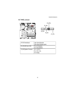
N J20 Front Panel Connector-- Power button and Power LED, H USB1 Front USB Connector
 |
View all Gigabyte GA-8IPXDR-E manuals
Add to My Manuals
Save this manual to your list of manuals |
Page 27 highlights
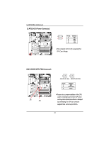
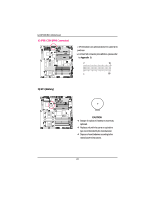
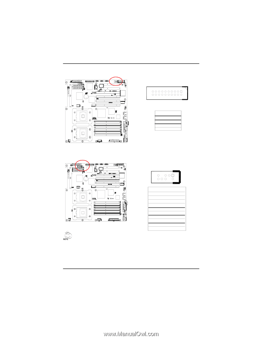
GA-8IPXDR-E(C) Motherboard N) J20 (Front Panel Connector-- Power button and Power LED) 1 20 Pin No. 17 18 19 20 Definition PWR LED+ PWR LEDPWR BTN+ PWR BTN- H) USB1 (Front USB Connector) 1 Be careful with the polarity of the front panel USB connector. Check the pin assignment while you connect the front panel USB cable. Please contact your nearest dealer for optional front panel USB cable. 27 Pin No. 1 2 3 4 5 6 7 8 9 10 Definition Power GND USB D2NC USB D2+ USB D3+ NC USBD3GND Power
-
 1
1 -
2
-
3
-
4
-
5
-
6
-
7
-
8
-
9
-
10
-
11
-
12
-
13
-
14
-
15
-
16
-
17
-
18
-
19
-
20
-
21
-
 22
22 -
 23
23 -
 24
24 -
 25
25 -
 26
26 -
 27
27 -
 28
28 -
 29
29 -
 30
30 -
 31
31 -
 32
32 -
33
-
34
-
35
-
36
-
37
-
38
-
39
-
40
-
41
-
42
-
43
-
44
-
45
-
46
-
47
-
48
-
49
-
50
-
51
-
52
-
53
-
54
-
55
-
56
-
57
-
58
-
59
-
60
-
61
-
62
-
63
-
64
-
65
-
66
-
67
-
68
-
69
-
70
 |
 |
27
GA-8IPXDR-E(C) Motherboard
N) J20 (Front Panel Connector-- Power button and Power LED)
Pin No.
Definition
17
PWR LED+
18
PWR LED-
19
PWR BTN+
20
PWR BTN-
1
20
H) USB1 (Front USB Connector)
Be careful with the polarity of the front
panel
USB connector. Check
the pin assignment
while you connect the front panel USB cable.
Please contact
your nearest dealer for
optional front panel USB cable.
1
Pin No.
Definition
1
Power
2
GND
3
USB D2-
4
NC
5
USB D2+
6
USB D3+
7
NC
8
USBD3-
9
GND
10
Power