Gigabyte GA-8IPXDR-E User Manual - Page 21
A ATX3 2x12 Pin ATX Power
 |
View all Gigabyte GA-8IPXDR-E manuals
Add to My Manuals
Save this manual to your list of manuals |
Page 21 highlights
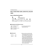
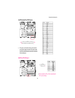
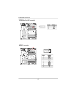
A) ATX3 (2x12 Pin ATX Power ) 24 13 12 1 ¾ AC power cord should only be connected to your power supply unit after ATX power cable and other related devices are firmly connected to the mainboard. Connector Introduction PIN No. 1 2 3 4 5 6 7 8 9 10 11 12 13 14 15 16 17 18 19 20 21 22 23 24 Definition +3.3V +3.3V GND +5V GND +5V GND POK 5VSB +12V +12V +3.3V +3.3V -12V GND PSON GND GND GND -5V +5V +5V +5V GND B) ATX1 (ATX1 Power ) Pin No. Definition 1 GND 2 +12v 3 GND 1 4 +12V 5 GND 6 +12V 7 GND 8 +12V ¾This connector (ATX +12V) is used only for CPU Core Voltage. 21
-
 1
1 -
2
-
3
-
4
-
5
-
6
-
7
-
8
-
9
-
10
-
11
-
12
-
13
-
14
-
15
-
 16
16 -
 17
17 -
 18
18 -
 19
19 -
 20
20 -
 21
21 -
 22
22 -
 23
23 -
 24
24 -
 25
25 -
 26
26 -
27
-
28
-
29
-
30
-
31
-
32
-
33
-
34
-
35
-
36
-
37
-
38
-
39
-
40
-
41
-
42
-
43
-
44
-
45
-
46
-
47
-
48
-
49
-
50
-
51
-
52
-
53
-
54
-
55
-
56
-
57
-
58
-
59
-
60
-
61
-
62
-
63
-
64
-
65
-
66
-
67
-
68
-
69
-
70
 |
 |

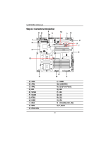
Connector Introduction
21
A) ATX3 (2x12 Pin ATX Power )
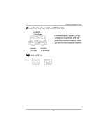
B) ATX1 (ATX1 Power )
This connector (ATX +12V) is used only for
CPU Core Voltage.
1
24
Pin No.
Definition
1
GND
2
+12v
3
GND
4
+12V
5
GND
6
+12V
7
GND
8
+12V
1
13
12
AC power cord should only be connected to
your power supply unit after ATX power cable
and other related devices are firmly connected
to the mainboard.
PIN No.
Definition
1
+3.3V
2
+3.3V
3
GND
4
+5V
5
GND
6
+5V
7
GND
8
POK
9
5VSB
10
+12V
11
+12V
12
+3.3V
13
+3.3V
14
-12V
15
GND
16
PSON
17
GND
18
GND
19
GND
20
-5V
21
+5V
22
+5V
23
+5V
24
GND