Gigabyte GA-VM900MC Manual
Gigabyte GA-VM900MC Manual
 |
View all Gigabyte GA-VM900MC manuals
Add to My Manuals
Save this manual to your list of manuals |
Gigabyte GA-VM900MC manual content summary:
- Gigabyte GA-VM900MC | Manual - Page 1
GA-VM900MC Intel® CoreTM 2 Duo / Intel® Pentium® D / Intel® Pentium® 4 / Celeron® D LGA775 Processor Motherboard User's Manual Rev. 1002 12ME-VM900MC-1002R * The WEEE marking on the product indicates this product must not be disposed of with user's other household waste and must be handed over - Gigabyte GA-VM900MC | Manual - Page 2
Motherboard GA-VM900MC Jun. 26, 2007 Motherboard GA-VM900MC Jun. 27, 2007 - Gigabyte GA-VM900MC | Manual - Page 3
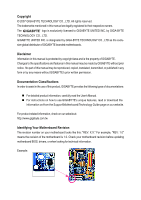
of documentations: „ For detailed product information, carefully read the User's Manual. „ For instructions on how to use GIGABYTE's unique features, read or download the information on/from the Support\Motherboard\Technology Guide page on our website. For product-related information, check on our - Gigabyte GA-VM900MC | Manual - Page 4
GA-VM900MC Motherboard Layout 7 Block Diagram ...8 Chapter 1 Hardware Installation 9 1-1 Installation Precautions 9 1-2 Product Specifications 2-2 The Main Menu 31 2-3 Standard CMOS Features 33 2-4 Advanced BIOS Features 35 2-5 IntegratedPeripherals 37 2-6 Power Management Setup 39 2-7 PnP - Gigabyte GA-VM900MC | Manual - Page 5
the SATA RAID Driver and Operating System 71 5-2 Configuring Audio Input and Output 74 5-2-1 Configuring 2/4/5.1/7.1-Channel Audio 74 5-2-2 Installing the S/PDIF In and Out Cable (Optional 77 5-2-3 Configuring Microphone Recording 79 5-2-4 Using the Sound Recorder 81 5-3 Troubleshooting 82 - Gigabyte GA-VM900MC | Manual - Page 6
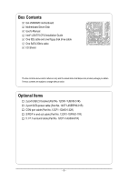
Box Contents GA-VM900MC motherboard Motherboard Driver Disk User's Manual Intel® LGA775 CPU Installation Guide One IDE cable and one floppy disk drive cable One SATA 3Gb/s cable I/O Shield The box contents above are for reference only and the actual - Gigabyte GA-VM900MC | Manual - Page 7
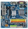
GA-VM900MC Motherboard Layout KB_MS LGA775 CPU_FAN COMA LPT ATX_12V VGA GA-VM900MC ATX USB USB LAN AUDIO F_AUDIO PCIE_16 Winbond W83627 VIA P4M900 DDRII1 DDRII2 DDR1 SYS_FAN IDE1 IDE2 RTL8201 PCIE_1 BIOS PCI1 CD_IN PCI2 CODEC HDA_SUR COMB FDD SPDIF_IO CLR_CMOS VIA VT8237S - Gigabyte GA-VM900MC | Manual - Page 8
Block Diagram PCIe CLK (100 MHz) D-Sub PCI Express x16 PCI Express Bus x1 PCIe CLK (100 MHz) PCI Express x1 BIOS RJ45 LAN PCI Bus RTL8201 LGA775 Processor CPU CLK+/- (266/200/133 MHz) Host Interface VIA P4M900 DDR2 667/533/400 MHz (Note) DDR2 DDR - Gigabyte GA-VM900MC | Manual - Page 9
, carefully read the user's manual and follow these procedures: • Prior to installation, do not remove or break motherboard S/N (Serial Number) sticker or you are uncertain about any installation steps or have a problem related to the use of the product, please consult a certified computer technician. - Gigabyte GA-VM900MC | Manual - Page 10
- Support for SATA RAID 0 and RAID 1 Š Winbond W83627 chip: - 1 x floppy disk drive connector supporting up to 1 floppy disk drive Š Integrated in the South Bridge Š Up to 8 USB 2.0/1.1 ports (4 on the back panel, 4 via the USB brackets connected to the internal USB headers) GA-VM900MC Motherboard - Gigabyte GA-VM900MC | Manual - Page 11
D-Sub port Š 4 x USB 2.0/1.1 ports Š 1 x RJ-45 port Š 3 x audio jacks (Line In/Line Out/Microphone) I/O Controller Š Winbond W83627 chip Hardware Monitor Š System voltage CPU fan speed control BIOS Š 1 x 4 Mbit flash Š Use of licensed AWARD BIOS Š PnP 1.0a, DMI 2.0, SM BIOS 2.3, ACPI 1.0b - Gigabyte GA-VM900MC | Manual - Page 12
is required if you wish to install DDR2 667 MHz memory. (Note 3) A 5.1/7.1 surround cable (optional) needs to be installed if you wish to enable 7.1-channel audio output. (Note 4) Available functions in Easytune may differ by motherboard model. GA-VM900MC Motherboard - 12 - - Gigabyte GA-VM900MC | Manual - Page 13
is optimized for HT Technology • A BIOS that supports HT Technology and has it enabled (Refer to Chapter 2, "BIOS Setup," "Advanced BIOS Features," for instructions on enabling the HT Technology.) 1-3-1 Installing the CPU A. Locate the alignment keys on the motherboard CPU socket and the notches on - Gigabyte GA-VM900MC | Manual - Page 14
English B. Follow the steps below to correctly install the CPU into the motherboard CPU socket. Before installing the CPU, make sure to turn off the computer and unplug inserted, replace the load plate and push the CPU socket lever back into its locked position. GA-VM900MC Motherboard - 14 - - Gigabyte GA-VM900MC | Manual - Page 15
that the Male and Female push pins are joined closely. (Refer to your CPU cooler installation manual for instructions on installing the cooler.) Step 5: After the installation, check the back of the motherboard. If the push pin is inserted as the picture above, the installation is complete. Step - Gigabyte GA-VM900MC | Manual - Page 16
Make sure that the motherboard supports the memory. It is recommended that memory of the same capacity, brand, speed, and chips be used. (Go to GIGABYTE's website for the latest memory support list.) • Always into place when the memory module is securely inserted. GA-VM900MC Motherboard - 16 - - Gigabyte GA-VM900MC | Manual - Page 17
an expansion card: • Make sure the motherboard supports the expansion card. Carefully read the manual that came with your expansion card. • Always If necessary, go to BIOS Setup to make any required BIOS changes for your expansion card(s). 7. Install the driver provided with the expansion card - Gigabyte GA-VM900MC | Manual - Page 18
to a back panel connector, first remove the cable from your device and then remove it from the motherboard. • When removing the cable, pull it straight out from the connector. Do not rock it side to side to prevent an electrical short inside the cable connector. GA-VM900MC Motherboard - 18 - - Gigabyte GA-VM900MC | Manual - Page 19
the multi-channel audio feature through the audio driver. Refer to the instructions on setting up a 2/4/5.1/7.1-channel audio configuration in Chapter 5, "Configuring 2/4/5.1/7.1Channel Audio." 1-7 Internal securely attached to the connector on the motherboard. - 19 - Hardware Installation - Gigabyte GA-VM900MC | Manual - Page 20
the power connector, the power supply can supply enough stable power to all the components on the motherboard. Before connecting the power connector, first make sure the power supply is turned off and all +5V +5V (Only for 2x12-pinATX) GND (Only for 2x12-pin ATX) GA-VM900MC Motherboard - 20 - - Gigabyte GA-VM900MC | Manual - Page 21
+12V voltage. The black connector wire is the ground wire. The motherboard supports CPU fan speed control, which requires the use of a CPU fan disk drive. The types of floppy disk drives supported are: 360 KB, 720 KB, 1.2 MB, 1.44 MB, and 2.88 MB. Before connecting a floppy disk drive, locate the - Gigabyte GA-VM900MC | Manual - Page 22
0 and RAID 1. Refer to Chapter 5, "Configuring SATA Hard Drive(s)," for instructions on configuring a RAID array. SATAII1 7 1 1 7 SATAII0 Pin No. 1 2 3 4 5 6 7 Definition GND TXP TXN GND RXN RXP GND A RAID 0 or RAID 1 configuration requires two hard drives. GA-VM900MC Motherboard - 22 - - Gigabyte GA-VM900MC | Manual - Page 23
2 MPD- 3 MPD- System Status LED S0 On S1 Blinking S3/S4/S5 Off 9) BATTERY The battery provides power to keep the values (such as BIOS configurations, date, and time information) in the CMOS when the computer is turned off. Replace the battery when the battery voltage drops to a low level - Gigabyte GA-VM900MC | Manual - Page 24
heard if no problem is detected at system startup. If a problem is detected, the BIOS may issue beeps in different patterns to indicate the problem. Refer to Chapter 5, "Troubleshooting," for information about assignments and the pin assignments are matched correctly. GA-VM900MC Motherboard - 24 - - Gigabyte GA-VM900MC | Manual - Page 25
10 NC • The front panel audio header supports HD audio by default. If your chassis provides an AC'97 front panel audio module, refer to the instructions on how to activate AC'97 functioninality via the audio software in Chapter 5, "Configuring 2/4/5.1/7.1-Channel Audio." • When using an AC'97 - Gigabyte GA-VM900MC | Manual - Page 26
to an audio device that supports digital audio out and an audio system that supports digital audio in. For purchasing the optional S/PDIF in and out cable, please contact the local dealer. 1 2 5 6 Pin No. 1 2 3 4 5 6 Definition Power No Pin SPDIF SPDIFI GND GND GA-VM900MC Motherboard - 26 - Gigabyte GA-VM900MC | Manual - Page 27
8 9 10 Definition NDCD BNSIN B NSOUT B NDTR BGND NDSR BNRTS BNCTS BNRI BNo Pin 16) F_USB1/F_USB2(USB Headers) The headers conform to USB 2.0/1.1 specification. Each USB header can provide two USB ports via an optional USB bracket. For purchasing the optional USB bracket, please contact the local - Gigabyte GA-VM900MC | Manual - Page 28
the jumper. Failure to do so may cause damage to the motherboard. • After system restart, go to BIOS Setup to load factory defaults (select Load Optimized Defaults) or manually configure the BIOS settings (refer to Chapter 2, "BIOS Setup," for BIOS configurations). GA-VM900MC Motherboard - 28 - - Gigabyte GA-VM900MC | Manual - Page 29
that searches and downloads the latest version of BIOS from the Internet and updates the BIOS. For instructions on using the Q-Flash and @BIOS utilities, refer to Chapter 4, "BIOS Update Utilities." • Because BIOS flashing is potentially risky, if you do not encounter problems using the current - Gigabyte GA-VM900MC | Manual - Page 30
, the device boot order will still be based on BIOS Setup settings. You can access Boot Menu again to change the first boot device setting as needed. : Q-Flash Press the key to access the Q-Flash utility directly without having to enter BIOS Setup first. GA-VM900MC Motherboard - 30 - - Gigabyte GA-VM900MC | Manual - Page 31
Supervisor Password Set User Password Save & Exit Setup Exit Without Saving KLJI: Select Item F10: Save & Exit Setup Time, Date, Hard Disk Type... BIOS Setup Program Function Keys Move the selection bar to select an item Execute command or enter the submenu Main Menu: Exit the - Gigabyte GA-VM900MC | Manual - Page 32
integrated audio, and BIOS Setup. (Pressing can also carry out this task.) „ Exit Without Saving Abandon all changes and the previous settings remain in effect. Pressing to the confirmation message will exit BIOS Setup. (Pressing can also carry out this task.) GA-VM900MC Motherboard - Gigabyte GA-VM900MC | Manual - Page 33
Mode Support BIOS automatically detect IDE/SATA devices during the POST. (Default) • None If no IDE/SATA devices are used, set this item to None so the system will skip the detection of the device during the POST for faster system startup. • Manual Allows you to manually enter the specifications - Gigabyte GA-VM900MC | Manual - Page 34
specifications. If you wish to enter the parameters manually Floppy 3 Mode Support Allows you to BIOS POST. Base Memory Also called conventional memory. Typically, 640 KB will be reserved for the MS-DOS operating system. Extended Memory The amount of extended memory. GA-VM900MC Motherboard - Gigabyte GA-VM900MC | Manual - Page 35
Setup Utility-Copyright (C) 1984-2007 Award Software Advanced BIOS Features Init Display First Dual display function VGA Share Note) This item is present only if you install a CPU that supports this feature. For more information about Intel CPUs' unique features, please visit Intel's website. - 35 - Gigabyte GA-VM900MC | Manual - Page 36
password is required for booting the system and for entering the BIOS Setup program. HDD S.M.A.R.T. Capability Enables or disables the S.M.A.R.T. ( a CPU that supports this feature. For more information about Intel CPUs' unique features, please visit Intel's website. GA-VM900MC Motherboard - 36 - - Gigabyte GA-VM900MC | Manual - Page 37
-in audio card instead of using the onboard audio, set this item to Disabled. LAN Controller Enables or disables the onboard LAN function. (Default: Enabled) If you wish to install a 3rd party add-in network card instead of using the onboard LAN, set this item to Disabled. - 37 - BIOS Setup - Gigabyte GA-VM900MC | Manual - Page 38
the integrated USB 2.0 controller. (Default: Enabled) USB Keyboard Support Allows USB keyboard to be used in MS-DOS. (Default: Disabled) USB Mouse Support Allows USB mouse to be used in MS-DOS. (Default to EPP or ECP+EPP mode. Options are: EPP 1.7 (default), EPP 1.9. GA-VM900MC Motherboard - 38 - - Gigabyte GA-VM900MC | Manual - Page 39
upon the return of the AC power. Memory The system returns to its last known awake state upon the return of the AC power. - 39 - BIOS Setup - Gigabyte GA-VM900MC | Manual - Page 40
on a specific day in a month. Resume Time (hh: mm: ss) : Set the time at which the system will be powered on automatically. Note: When using this function, avoid inadequate shutdown from the operating system or removal of the AC power, or the settings may not be effective. GA-VM900MC Motherboard - Gigabyte GA-VM900MC | Manual - Page 41
IRQ Assignment Auto 3,4,5,7,9,10,11,12,14,15 +/-/PU/PD: Value F10: Save F6: Fail-Safe Defaults ESC: Exit F1: General Help F7: Optimized Defaults BIOS auto-assigns IRQ to the first PCI slot. (Default) Assigns IRQ 3,4,5,7,9,10,11,12,14,15 to the first PCI slot - Gigabyte GA-VM900MC | Manual - Page 42
the warning threshold for system/CPU temperature. When system/CPU temperature exceeds the threshold, BIOS will emit warning sound. Options are: Disabled (default), 60oC/140oF, 70oC/158oF, 80oC/176oF, 90oC/194oF disabled, CPU fan runs at full speed. (Default: Enabled) GA-VM900MC Motherboard - 42 - - Gigabyte GA-VM900MC | Manual - Page 43
this item and then press the key to load the safest BIOS default settings. In case system instability occurs, you may try to load Fail-Safe defaults, which are the safest and most stable BIOS settings for the motherboard. 2-10 Load Optimized Defaults CMOS Setup Utility-Copyright (C) 1984-2007 - Gigabyte GA-VM900MC | Manual - Page 44
allows you to view the BIOS settings but not to make changes. To clear the password, press on the password item and when requested for the password, press again. The message "PASSWORD DISABLED" will appear, indicating the password has been cancelled. GA-VM900MC Motherboard - 44 - - Gigabyte GA-VM900MC | Manual - Page 45
Press on this item and press the key. This saves the changes to the CMOS and exits the BIOS Setup program. Press or to return to the BIOS Setup Main Menu. 2-13 Exit Without Saving CMOS Setup Utility-Copyright (C) 1984-2007 Award Software ` Standard CMOS Features ` Advanced - Gigabyte GA-VM900MC | Manual - Page 46
English GA-VM900MC Motherboard - 46 - - Gigabyte GA-VM900MC | Manual - Page 47
other drivers. • After the drivers are installed, follow the onscreen instructions to restart your system. You can install other applications included in the motherboard driver disk. • For USB 2.0 driver support under the Windows XP operating system, please install the Windows XP Service Pack - Gigabyte GA-VM900MC | Manual - Page 48
all the tools and applications that GIGABYTE develops and some free software. You may press the Install button following an item to install it. 3-3 Driver CD Information This page provides information about the drivers, applications and tools in this driver disk. GA-VM900MC Motherboard - 48 - - Gigabyte GA-VM900MC | Manual - Page 49
English 3-4 Hardware Information This page provides information about the hardware devices on this motherboard. 3-5 Contact Us Check the contacts information of the GIGABYTE headquarter in Taiwan and the overseas branch offices on the last page of this manual. - 49 - Drivers Installation - Gigabyte GA-VM900MC | Manual - Page 50
English GA-VM900MC Motherboard - 50 - - Gigabyte GA-VM900MC | Manual - Page 51
system data and perform restoration of it. Supporting NTFS, FAT32, and FAT16 file systems, your system soon after the operating system and drivers are installed. • The amount of data and Requirements: • Intel® x86 platform • At least 64 MB of system memory • VESA compatible graphics card • Windows® - Gigabyte GA-VM900MC | Manual - Page 52
Hard Drive 1. Set CD-ROM drive as the first boot device under "Advanced BIOS Features" in the BIOS Setup program. Save the changes and exit. 2. When partitioning your hard drive for example, NTFS) and begin the installation of the operating system (Figure 3). Figure 3 GA-VM900MC Motherboard - 52 - - Gigabyte GA-VM900MC | Manual - Page 53
Figure 4 Figure 5 5. If your hard drive is not properly partitioned before you install the operating system, you may create new partitions using free space on your hard drive (Figure 6, 7). However, if Disk Management shows the hard drive only contains the System partition without any unallocated - Gigabyte GA-VM900MC | Manual - Page 54
Boot from the motherboard driver disk to access Award Modular BIOS v6.00PG, An Energy Star Ally Copyright (C) 1984-2007, Award Software, Inc. VM900MC E3 . . . . : BIOS Setup/Q- to check disk allocation. Figure 12 GA-VM900MC Motherboard Xpress Recovery2 will automatically create a new partition to - Gigabyte GA-VM900MC | Manual - Page 55
English D. Using the Restore Function in Xpress Recovery2 Select RESTORE to restore the backup to your hard drive in case the system breaks down. The RESTORE option will not be present if no backup is created before (Figure 13, 14). Figure 13 Figure 14 E. Removing the Backup 1. If you wish to - Gigabyte GA-VM900MC | Manual - Page 56
server site and update the BIOS. 4-2-1 Updating the BIOS with the Q-Flash Utility A. Before You Begin: 1. From GIGABYTE's website, download the latest compressed BIOS update file that matches your motherboard model. 2. Extract the file and save the new BIOS file (e.g. VM900MC.F1) to your floppy - Gigabyte GA-VM900MC | Manual - Page 57
KL:Move ESC:Reset :Power Off Total size : 0 Free size : 0 3. Select the BIOS update file and press . Make sure the BIOS update file matches your motherboard model. Step 2: The process of the system reading the BIOS file from the floppy disk is displayed on the screen. When - Gigabyte GA-VM900MC | Manual - Page 58
Quit F8: Q-Flash KLJI: Select Item F10: Save & Exit Setup Load Optimized Defaults Press to load BIOS defaults Step 6: Select Save & Exit Setup and then press to save settings to CMOS and exit BIOS Setup. The procedure is complete after the system restarts. GA-VM900MC Motherboard - 58 - - Gigabyte GA-VM900MC | Manual - Page 59
and Using @BIOS: Use the motherboard driver disk included with the motherboard to install @BIOS. • Installing the @BIOS utility. • Accessing the @BIOS utility. Click Start>Program>Gigabyte>@BIOS Select @BIOS and click Install. C. Options and Instructions: 1. Save the Current BIOS File In the - Gigabyte GA-VM900MC | Manual - Page 60
could result in an unbootable system. • If the BIOS update file for your motherboard is not present on the @BIOS server site, please manually download the BIOS update file from GIGABYTE's website and follow the instructions in "Update the BIOS without Using the Internet Update Function" below. Step - Gigabyte GA-VM900MC | Manual - Page 61
BIOS Setup program. EasyTune 5 provides the following functions (Note 1): overclocking/overvoltage, C.I.A./ M.I.B. (Note 2), smart fan control, and hardware monitoring and warning. (For instructions on using EasyTune5, read or download the information on/from the Support\Motherboard Visits GIGABYTE - Gigabyte GA-VM900MC | Manual - Page 62
the slider or spin box. Click Apply and then OK to turn on ReadyBoost. • The USB flash drive must have at least 256 MB of space. • The recommended amount of memory to use for ReadyBoost acceleration is one to three times the amount of RAM installed in your computer. GA-VM900MC Motherboard - 62 - - Gigabyte GA-VM900MC | Manual - Page 63
BIOS Setup. C . Configure a RAID array in RAID BIOS. (Note 1) D. Make a floppy disk containing the SATA RAID driver. (Note 2) E. Install the SATA RAID driver floppy disk. • Windows Vista/XP/2000 setup disk. • Motherboard driver disk. 5-1-1 Configuring VIA VT8237S SATA Controllers A. Installing SATA - Gigabyte GA-VM900MC | Manual - Page 64
USB Keyboard Support USB Mouse Support Onboard BIOS Setup. The BIOS Setup menus described in this section may differ from the exact settings for your motherboard. The actual BIOS Setup menu options you will see shall depend on the motherboard you have and the BIOS version. GA-VM900MC Motherboard - Gigabyte GA-VM900MC | Manual - Page 65
Ctrl+Z into User Window!" (Figure 2). Press + to enter the RAID Configuration Utility. VIA Technologies, Inc. VIA VT8237S V-RAID CDROM BOOT BIOS V1.20 Copyright (C) VIA Technologies, Inc. All Right reserved. 237SR120.ROM-FOR RAID Scan Devices, Please wait... No Raid Channel0 Master - Gigabyte GA-VM900MC | Manual - Page 66
RAID mode. Select Array Mode and press . And the RAID mode selection menu will appear (Figure 5). The supported RAID modes include RAID 0 for performance, RAID 1 for data protection, and RAID SPAN for capacity. Use the Status 111.79 Hdd 111.79 Hdd Figure 5 GA-VM900MC Motherboard - 66 - - Gigabyte GA-VM900MC | Manual - Page 67
English After selecting a RAID mode, you must decide whether you want the RAID array to be configured automatically or manually. Auto Setup allows BIOS to assign the hard drives and create arrays automatically. It is recommended all hard drives are new ones when you want to create an array. - Gigabyte GA-VM900MC | Manual - Page 68
to next item Confirm the selection Exit Stripe Size 64K ST3120026AS ST3120026AS Cap. (GB) 223.58 111.79 111.79 Status Normal Stripe0 Stripe1 Figure 9 GA-VM900MC Motherboard - 68 - - Gigabyte GA-VM900MC | Manual - Page 69
English Serial Number View: Highlight Serial Number View and press . Use the ARROW keys to select a drive, and the selected drive's serial number can be viewed at the bottom line (Figure 10). The serial number is assigned by the disk drive manufacturer . VIA VT8237S V-RAID Utility V1.20 X - Gigabyte GA-VM900MC | Manual - Page 70
For users without a startup disk: Use an alternative system and insert the motherboard driver disk. From your optical drive folder, double click the MENU.exe file in the BootDrv folder (Figure 3). A command prompt window will open similar to that in Figure 2. GA-VM900MC Motherboard Figure 3 - 70 - - Gigabyte GA-VM900MC | Manual - Page 71
SATA RAID driver diskette and configured the required BIOS settings, driver and press (Figure 2). Windows Setup Setup could not determine the type of one or more mass storage devices installed in your system, or you have chosen to manually specify an adapter. Currently, Setup will load support - Gigabyte GA-VM900MC | Manual - Page 72
begin to load the SATA Raid driver from the floppy disk. Windows Setup You have chosen to configure a SCSI Adapter for use with Windows, using a device support disk provided by an adapter manufacturer. select VIA V-RAID Controller Series (Windows XP/SRV2003-x64). GA-VM900MC Motherboard - 72 - - Gigabyte GA-VM900MC | Manual - Page 73
English Step 4: After the SATA RAID driver installation is completed, you can proceed with the Windows XP installation. WindowsXP Professional Setup Welcome to Setup. This port of the Setup program prepares Microsoft(R) - Gigabyte GA-VM900MC | Manual - Page 74
out. • 4 channel audio: Front speaker out and Rear speaker out. • 5.1 channel audio: Front speaker out, Rear speaker out, and Center/Subwoofer speaker out. • 7.1 channel audio: Front speaker out, Rear speaker out, Center/Subwoofer speaker out, and Side speaker out. GA-VM900MC Motherboard - 74 - - Gigabyte GA-VM900MC | Manual - Page 75
-click the icon to access the Audio Control Panel. Before installing the audio driver, make sure the "Microsoft UAA Bus driver for High Defintion Audio" has been installed from the motherboard driver disk and your operating system has been updated with the latest Service Pack for Windows. - 75 - Gigabyte GA-VM900MC | Manual - Page 76
Disable front panel jack detection check box. Click OK to activiate the AC'97 functionality. When using an AC'97 front panel audio module, you can only have audio signals present on either the front or the back panel audio connections, but not both at the same time. GA-VM900MC Motherboard - 76 - - Gigabyte GA-VM900MC | Manual - Page 77
out cable first if you want to output S/PDIF digital audio signals to an external decoder. A. Installing the S/PDIF In and Out Cable: Step 1: First, attach the connector at the end of the cable to the SPDIF_IO header on your motherboard. Step 2: Secure the metal bracket to the chassis back panel - Gigabyte GA-VM900MC | Manual - Page 78
PDIF digital audio signals. S/PDIF Optical Cable B. Configuring S/PDIF out: Click the tool icon in the DIGITAL section. In the S/PDIF In/Out Settings dialog box, select an output sampling rate and select (or disable) the output source. Click OK to complete the configuration. GA-VM900MC Motherboard - Gigabyte GA-VM900MC | Manual - Page 79
English 5-2-3 Configuring Microphone Recording Step 1: After installing the audio driver, the Audio Manager icon will appear in your system tray. Double-click the icon to access the Audio Control Panel. Step 2: Connect your microphone to the Mic in jack (pink) or the Line in jack (blue) on the back - Gigabyte GA-VM900MC | Manual - Page 80
list, select Realtek HD Audio Input. Then set the recording sound level properly. Do NOT mute the recording sound, or you will not hear any sound when playing back the recording you just made. Select Realtek HD Audio Input in the Mixer devie list GA-VM900MC Motherboard Recording Control - 80 - - Gigabyte GA-VM900MC | Manual - Page 81
, point to Programs, point to Accessories, point to Entertainment, and then click Sound Recorder to begin the sound recording. 5-2-4 Using the Sound Recorder Recording the Sound: 1. Make sure you have connected the audio input device (e.g. microphone) to the computer. 2. On the File menu, choose New - Gigabyte GA-VM900MC | Manual - Page 82
English 5-3 Troubleshooting 5-3-1 Frequently Asked Questions To read more FAQs for your motherboard, please go to the Support\Motherboard\FAQ page on GIGABYTE's website. Q: In the BIOS Setup program, why are some BIOS options missing? A: Some advanced options are hidden in the BIOS Setup program. - Gigabyte GA-VM900MC | Manual - Page 83
Procedure If you encounter any troubles during system startup, follow the troubleshooting procedure below to solve the problem. START Turn off the power. Remove all peripherals, connecting cables, and power cord etc. Make sure the motherboard does not short-circuit with the chassis or - Gigabyte GA-VM900MC | Manual - Page 84
exit BIOS Setup. No The keyboard or mouse might fail. The problem is problem, contact the place of purchase or local dealer for help. Or go to the Support\Technical Service Zone page to submit your question. Our customer service staff will reply you as soon as possible. GA-VM900MC Motherboard - Gigabyte GA-VM900MC | Manual - Page 85
- 85 - Appendix English - Gigabyte GA-VM900MC | Manual - Page 86
TEL: +86-24-83992901 FAX: +86-24-83992909 India GIGABYTE TECHNOLOGY (INDIA) LIMITED WEB address : http://www.giga-byte.co.in/ Saudi Arabia WEB address : http://www.gigabyte.com.sa Australia GIGABYTE TECHNOLOGY PTY. LTD. WEB address : http://www.gigabyte.com.au GA-VM900MC Motherboard - 86 - - Gigabyte GA-VM900MC | Manual - Page 87
Representative Office Of GIGA-BYTE Technology Co., Ltd. in SERBIA & MONTENEGRO WEB address : http://www.gigabyte.co.yu You may go to the GIGABYTE website, select your language in the language list on the top right corner of the website. GIGABYTE Global Service System To submit a technical - Gigabyte GA-VM900MC | Manual - Page 88
- 88 -
-
 1
1 -
 2
2 -
 3
3 -
 4
4 -
 5
5 -
 6
6 -
 7
7 -
8
-
9
-
10
-
11
-
12
-
13
-
14
-
15
-
16
-
17
-
18
-
19
-
20
-
21
-
22
-
23
-
24
-
25
-
26
-
27
-
28
-
29
-
30
-
31
-
32
-
33
-
34
-
35
-
36
-
37
-
38
-
39
-
40
-
41
-
42
-
43
-
44
-
45
-
46
-
47
-
48
-
49
-
50
-
51
-
52
-
53
-
54
-
55
-
56
-
57
-
58
-
59
-
60
-
61
-
62
-
63
-
64
-
65
-
66
-
67
-
68
-
69
-
70
-
71
-
72
-
73
-
74
-
75
-
76
-
77
-
78
-
79
-
80
-
81
-
82
-
83
-
84
-
85
-
86
-
87
-
88
 |
 |

GA-VM900MC
Intel
®
Core
TM
2 Duo / Intel
®
Pentium
®
D /
Intel
®
Pentium
®
4 / Celeron
®
D LGA775 Processor Motherboard
User's Manual
Rev. 1002
12ME-VM900MC-1002R
*
The WEEE marking on the product indicates this product must not be disposed of with user's other household waste
and must be handed over to a designated collection point for the recycling of waste electrical and electronic equipment!!
*
The WEEE marking applies only in European Union's member states.