Gigabyte GA-Z77X-UP7 Manual - Page 26
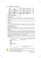
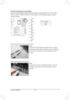
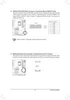
Onboard Voltage Measurement Module, the red wire is the positive and must be connected to the pin 1
 |
View all Gigabyte GA-Z77X-UP7 manuals
Add to My Manuals
Save this manual to your list of manuals |
Page 26 highlights
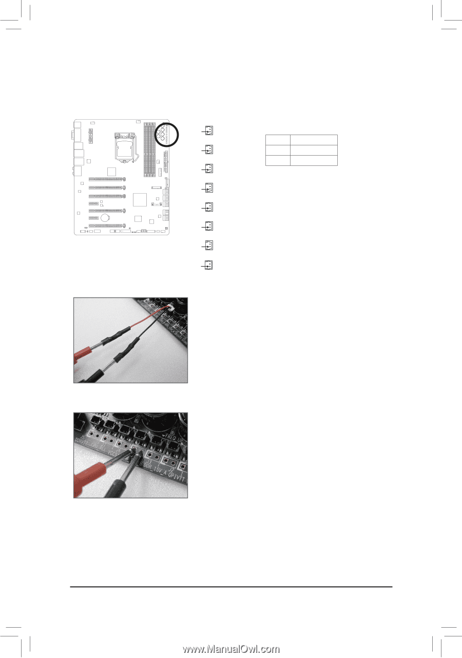
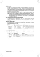
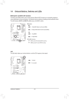
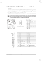
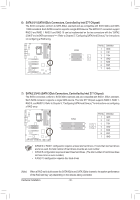
1 DIP 1 23 Onboard Voltage Measurement1 Module DIP Users can use a multimeter to measure component vo1 2l3tages, including VCORE, CPU VTT, IMC, VAXG, CPU PLL, DDR VTT, VDIMM, and PC1 HIO. You can emDIPploy one of the following two ways to measure component voltages. Method I (Using the included voltage measurement cable): Steps: Connect the included voltage measurement cable to a voltage measurement header and your multimeter as shown. Please note the red wire is the positive and must be connected to the pin 1 (Power). Method II (Connecting the multimeter directly): Steps: Connect the red lead of the multimeter to the pin 1 (Power) of a voltage measurement point and the black lead to the pin 2 (ground). Hardware Installation F_USB30 F_USB30 F_USB30 F_USB30 F_USB30F_AFU_DUISOB(H3)0F_AFU_DUISOB(3H0)F_AFU_UDSIOB(3H0)F_AUDIO(H)F_AUDIO(H)F_AUDIOF(H_P)FA_NAEULD(NIOH(FH)_)PFA_ANUEDL(INOH(FH)_)PANEL(NHF)_PANEL(NHF)_PANEL(NHF)F_P_APANNEEL(LNHF)_FP_APNAENLE(LNHF)_FP_APNAENLE(NLH)F_PAN (H61M-D2) (H61M-D2) (H61M-D2) (H61M - 26 - DIP 1 23 1 DIP 1 23 1 DIP 1 23 1 DIP 1 23 1 DIP 1 23 1 DIP 1 23 1 DIP 1 23 1 DIP 1 23 1 DIP 1 23 DIP 1 23 DIP 1 23 DIP 1 23 DIP 1 23 DIP 1 23 DIP 1 23 DIP 1 23 VCORE DIP 1 23 1 Pin 1 CPUVTT DIP 1 23 1 Pin 1 DB_PORT DB_PORT DB_PORT DB_POBRITOSDSBw_itPcOheRBrITO(XS5D8SBAw_-iOPtcCOh)eRBrTIO(XS5D8SBAw_-iPOtcOChRBe) rTIO(XSD5S8BAw_-iPtOcOhCReB)rTIO(XS58SAw-iOtcCheB) rIO(XS5S8Aw-iOtcChBe)rIO(XS5S8Aw-itOchCeB)rIO(XS5S8Aw-iOtcChe)r (X58A-OC) 1 1 1 1 1 1 1 1 1 1 1 1 1 1 1 1 M_SATA M_SATA M_SATA M_SATA M_SATA M_SATA M_SATA M_SATA 1 1 Pin 1 Pin 1 1 Pin 1 Pin 1 TPM w/housing TPM w/housing TPM w/housing TPM w/housing ACPI_CPT ACPI_CPT ACPI_CPT ACPI_ Voltage measVuoreltamgeenmt meaosdVuorlleta(mXge5en8mtAme-OaosVCduou)rletam(gXe5n8mtAme-aOosVdCuou)rleteam(gXee5n8mtAme-aOosVdCuuor)letam(gXe5n8mtAme-aOosVdCuou)rleteam(gXe5nm8tAme-aOosVdCuour)lleteam(gXe5nm8tAme-aOosdCuur)leem(Xe5n8tAm-OodCu)le(X58A-OC) (GA-IVB) (GA-IVB) (GA-IVB) (GA-IV TPM TPM TPM TPM w/housing w/housing w/housing w/housing PWM Switch P(XW5M8AS-OwCitc)hP(XW5M8AS-OwiCtc)hP(WX5M8AS-wOiCtc)hP(XW5M8AS-OwiCtc)hP(XW5M8AS-wOiCtc)hP(WX5M8AS-wOiCtc)hP(XW5M8AS-wOiCtc)h (X58A-OC) IMC VAXG CPUPLL Pin 1 DDRVTT Pin 1 VDIMM PCHIO DIP 1 23 1 23 DIP DIP 1 23 1 23 DIP DIP 1 23 DIP 1 23 DIP 1 23 1 23 DIP 1 23 DIP 1 23 PCIe power cPoCnnIeecptoowr e(Sr AcPToCAnIn)e(eXpc5too8wrAe(-SOr AcPCoTC)nAIne)(eXpc5oto8wrAe(-rSOcAPCoTCn)AIne)e(Xpc5too8wrAe(-SrOAcPCoTCnA)In)e(eXpc5oto8wrAe(-SrOcAPCoTCn)AIne)(eXpco5tow8rAe(-rSOcAPCoTCn)AIne)e(Xpcot5ow8rAe(Sr-OcAoCTnA)n)e(Xc5to8rA(-SOACT)A)(X58A-OC) DIP 1 23 DIP SMB1 _2 C3 PT SMB_CPT SMB_CPT SMB_ (GA-IVB) (GA-IVB) (GA-IVB) (GA-IV Voltage measVuoreltamgeenmt peoainsVutosr(letGamg1ee.SnmtnpiepoaeisVnruto3srl)e(taGmg1e.nSmtnpeipoaeisVnruot3srle)t(aGmgB1eeI.nOSmtnSpeipoaSeisnVwrutois3rtlce(t)Gahmge1Ber.InSO(mtSnSpeWipoaSe4isVnrw)uot3sirltet)(caGmhge1Ber.InSOm(tSnSpeiWpoaSeisV4nrwu)ot3sriltet()caGmhg1Bee.rnISOm(tnSSpeiWpoaSeisn4wrut)s3rite()cGmh1eBe.rnISO(tnSpSiWpoSein4rwt)3sit()cGh1eB.rSIO(nSSipWeS4rw)3it)chBerIO(SSWS4w)itcheBrIO(SSWS4w)itcher (SW4) 2 GND Pin No. Definition 1 Power CLR_CMOS CLR_CMOS CLR_CMOSCLR_ CI CI CI CI DIS_ME DIS_ME DIS_ME DIS_M GP15_CPT GP15_CPT GP15_CPT GP15 (GA-IVB) (GA-IVB) (GA-IVB) (GA-IV XDP_CPU XDP_CPU XDP_CPU XDP_ XDP_PCH XDP_PCH XDP_PCH XDP_ (GA-IVB) (GA-IVB) (GA-IVB) (GA-IV
-
 1
1 -
2
-
3
-
4
-
5
-
6
-
7
-
8
-
9
-
10
-
11
-
12
-
13
-
14
-
15
-
16
-
17
-
18
-
19
-
20
-
 21
21 -
 22
22 -
 23
23 -
 24
24 -
 25
25 -
 26
26 -
 27
27 -
 28
28 -
 29
29 -
 30
30 -
 31
31 -
32
-
33
-
34
-
35
-
36
-
37
-
38
-
39
-
40
-
41
-
42
-
43
-
44
-
45
-
46
-
47
-
48
-
49
-
50
-
51
-
52
-
53
-
54
-
55
-
56
-
57
-
58
-
59
-
60
-
61
-
62
-
63
-
64
-
65
-
66
-
67
-
68
-
69
-
70
-
71
-
72
-
73
-
74
-
75
-
76
-
77
-
78
-
79
-
80
-
81
-
82
-
83
-
84
-
85
-
86
-
87
-
88
-
89
-
90
-
91
-
92
-
93
-
94
-
95
-
96
-
97
-
98
-
99
-
100
-
101
-
102
-
103
-
104
-
105
-
106
-
107
-
108
-
109
-
110
-
111
-
112
-
113
-
114
-
115
-
116
-
117
-
118
-
119
-
120
-
121
-
122
-
123
-
124
-
125
-
126
-
127
-
128
 |
 |