Gigabyte GA-Z77X-UP7 Manual - Page 33
F_AUDIO Front Panel Audio Header, SPDIF_IN S/PDIF In Header
 |
View all Gigabyte GA-Z77X-UP7 manuals
Add to My Manuals
Save this manual to your list of manuals |
Page 33 highlights
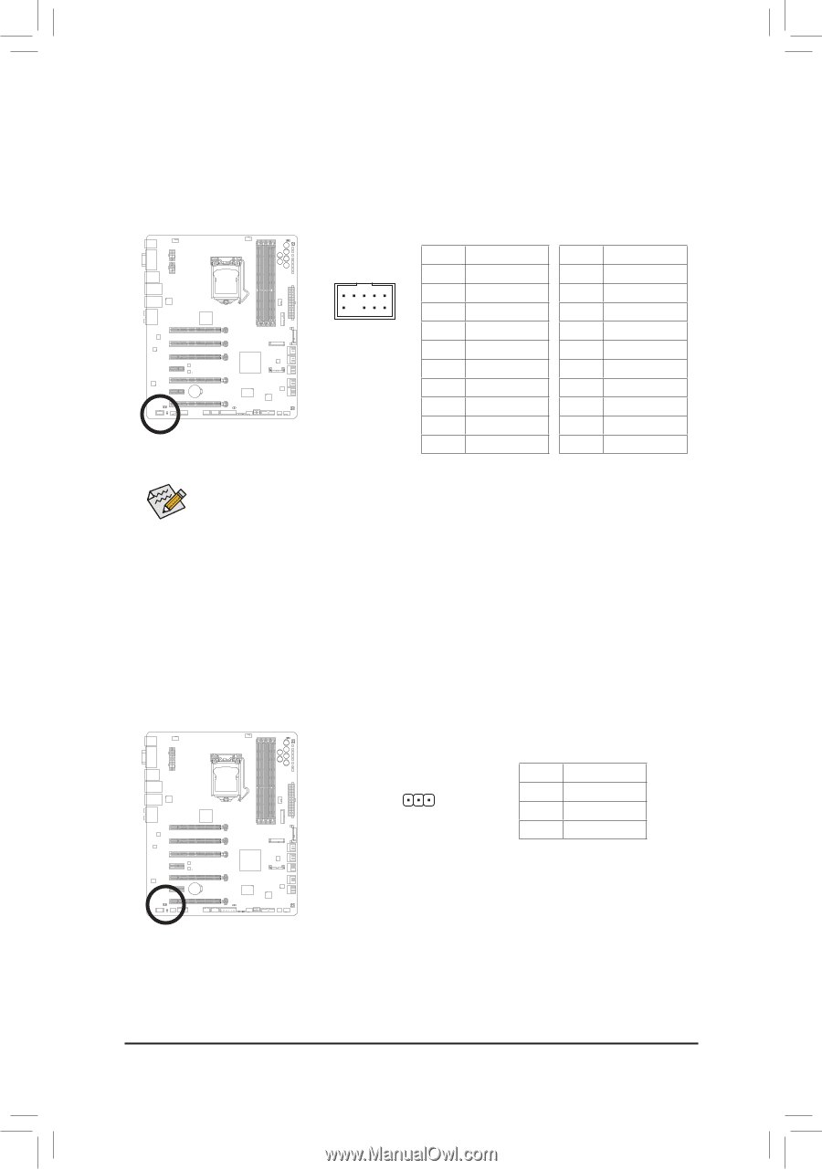
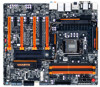
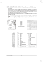
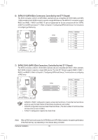
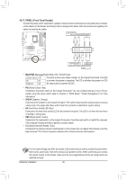
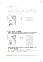
11) F_AUDIO (Front Panel Audio Header) The front panel audio header supports Intel High Definition audio (HD) and AC'97 audio. You may connect your chassis front panel audio module to this header. Make sure the wire assignments of the module connector match the pin assignments of the motherboard header. Incorrect connection between the module connector and the motherboard header will make the device unable to work or even damage it. F_AUDIO(H) For HD Front Panel Audio: For AC'97 Front Panel Audio: Pin No. Definition Pin No. Definition 9 1 1 MIC2_L 1 MIC F2_PANELG(NNHD) 3 MIC2_R 2 GND 3 MIC Power F_PANEL (H61M-D2) 10 2 4 -ACZ_DET 4 NC 5 LINE2_R 5 Line Out (R) 6 GND 6 NC 7 FAUDIO_JD 7 NC 8 No Pin 8 No Pin 9 LINE2_L 9 Line Out (L) 10 GND 10 NC DIP 1 23 1 DB_PORT BIOS Switcher (X58A-OC) •• The front panel audio header supports HD audio by default. If your chassis provides an AC'97 1 front panel audio module, refer to the instructions on how to activate AC'97 functionality via the audio software in Chapter 5, "Configuring 2/4/5.M1_/S7A.1TA-Channel Audio." DIP 1 23 1 DIP 1 23 1 •• Audio signals will be present on both of the front and back panel audio connections simultaneously. If you want to mute the back panel audio (only supported when using an HD front panel audioACPI_CPT Voltage measuremmeontdmuoledu)l,er(Xe5fe8Ar-tOoCC) hapter 5, "Configuring 2/4/5.1/7.1-Channel Audio." (GA-IVB) •• Some chassis provide a frPoWnMt pSwaintcehl(Xa5u8dAi-oOCm) odule that has separated connectors on each wire instead of a single plug. For information about connecting the front panel audio module that has different wire assignments, please contact the chassis manufacturer. DIP 1 23 SMB_CPT 12) SPDIF_IN (S/PDIF In Header) (GA-IVB) TPhCiIse phoewaedr ecornsnuecptopro(SrtAsTdA)ig(Xi5ta8Al S-O/CP)DIF In and can connect to an audio device that supports digital audio out via an optional S/PDIF In cable. For purchasing the optional S/PDIF In cable, please contact the local dealer. 1 age measurement points(G1.Sniper 3) BIOS Switcher (SW4) Pin No. 1 2 3 Definition Power SPDIFI GND CLR_CMOS CI DIS_ME GP15_CPT (GA-IVB) XDP_CPU XDP_PCH (GA-IVB) - 33 - Hardware Installation
-
 1
1 -
2
-
3
-
4
-
5
-
6
-
7
-
8
-
9
-
10
-
11
-
12
-
13
-
14
-
15
-
16
-
17
-
18
-
19
-
20
-
21
-
22
-
23
-
24
-
25
-
26
-
27
-
 28
28 -
 29
29 -
 30
30 -
 31
31 -
 32
32 -
 33
33 -
 34
34 -
 35
35 -
 36
36 -
 37
37 -
 38
38 -
39
-
40
-
41
-
42
-
43
-
44
-
45
-
46
-
47
-
48
-
49
-
50
-
51
-
52
-
53
-
54
-
55
-
56
-
57
-
58
-
59
-
60
-
61
-
62
-
63
-
64
-
65
-
66
-
67
-
68
-
69
-
70
-
71
-
72
-
73
-
74
-
75
-
76
-
77
-
78
-
79
-
80
-
81
-
82
-
83
-
84
-
85
-
86
-
87
-
88
-
89
-
90
-
91
-
92
-
93
-
94
-
95
-
96
-
97
-
98
-
99
-
100
-
101
-
102
-
103
-
104
-
105
-
106
-
107
-
108
-
109
-
110
-
111
-
112
-
113
-
114
-
115
-
116
-
117
-
118
-
119
-
120
-
121
-
122
-
123
-
124
-
125
-
126
-
127
-
128
 |
 |