Gigabyte GA-Z77X-UP7 Manual - Page 34
SPDIF_O S/PDIF Out Header, F_USB1/F_USB2 USB 2.0/1.1 Headers, the ON/OFF Charge function.
 |
View all Gigabyte GA-Z77X-UP7 manuals
Add to My Manuals
Save this manual to your list of manuals |
Page 34 highlights
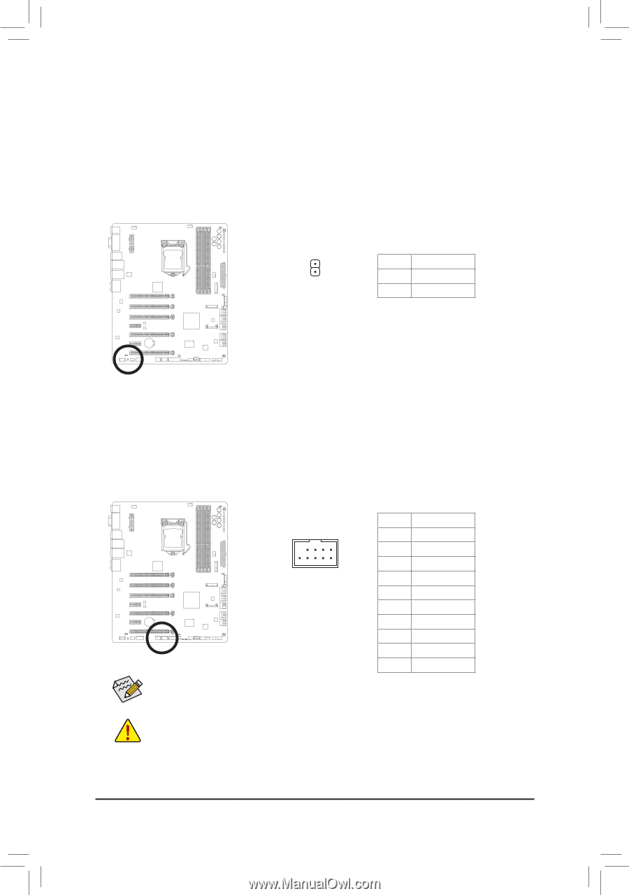
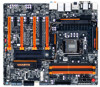
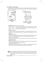
13) SPDIF_O (S/PDIF Out Header) This header supports digital S/PDIF Out and connects a S/PDIF digital audio cable (provided by expansion cards) for digital audio output from your motherboard to certain expansion cards like graphics cards and sound cards. For example, some graphics cards may require you to use a S/PDIF digital audio cable for digital audio output from your motherboard to your graphics card if you wish to connect an HDMI display to the graphics card and have digital audio output from the HDMI display at the same time. For information about connecting the S/PDIF digital audio cable, carefully read the manual for your expansion card. G.QBOFM Pin No. Definition 1 SPDIFO 1 2 GND 14) F_USB1/F_USB2 (USB 2.0/1.1 Headers) The headers conform to USB 2.0/1.1 specification. Each USB header can provide two USB ports via an optional USB bracket. For purchasing the optional USB bracket, please contact the local dealer. Pin No. Definition 1 Power (5V) 9 1 2 Power (5V) 10 2 3 USB DX- 4 USB DY- 5 USB DX+ 6 USB DY+ 7 GND 8 GND 9 No Pin 10 NC When the system is in S4/S5 mode, only the USB ports routed to the F_USB1 header can support the ON/OFF Charge function. •• Do not plug the IEEE 1394 bracket (2x5-pin) cable into the USB 2.0/1.1 header. •• Prior to installing the USB bracket, be sure to turn off your computer and unplug the power cord from the power outlet to prevent damage to the USB bracket. Hardware Installation - 34 -
-
 1
1 -
2
-
3
-
4
-
5
-
6
-
7
-
8
-
9
-
10
-
11
-
12
-
13
-
14
-
15
-
16
-
17
-
18
-
19
-
20
-
21
-
22
-
23
-
24
-
25
-
26
-
27
-
28
-
 29
29 -
 30
30 -
 31
31 -
 32
32 -
 33
33 -
 34
34 -
 35
35 -
 36
36 -
 37
37 -
 38
38 -
 39
39 -
40
-
41
-
42
-
43
-
44
-
45
-
46
-
47
-
48
-
49
-
50
-
51
-
52
-
53
-
54
-
55
-
56
-
57
-
58
-
59
-
60
-
61
-
62
-
63
-
64
-
65
-
66
-
67
-
68
-
69
-
70
-
71
-
72
-
73
-
74
-
75
-
76
-
77
-
78
-
79
-
80
-
81
-
82
-
83
-
84
-
85
-
86
-
87
-
88
-
89
-
90
-
91
-
92
-
93
-
94
-
95
-
96
-
97
-
98
-
99
-
100
-
101
-
102
-
103
-
104
-
105
-
106
-
107
-
108
-
109
-
110
-
111
-
112
-
113
-
114
-
115
-
116
-
117
-
118
-
119
-
120
-
121
-
122
-
123
-
124
-
125
-
126
-
127
-
128
 |
 |