Gigabyte MSH61DK Manual - Page 25
F_USB1 USB Headers, F_AUDIO Front Panel Audio Header
 |
View all Gigabyte MSH61DK manuals
Add to My Manuals
Save this manual to your list of manuals |
Page 25 highlights
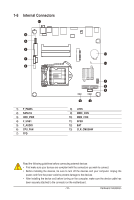
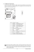
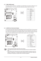
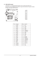
F_PANEL 4) F_USB1 (USB Headers) IR The headers conform to USB 2.0/1.1 specification. Each USB header can provide two USB ports CvOiaMBan optional USB bracket. For purchasing the optional USB bracket, please contact the local dealer. PWR_LED CLR_CMOS BIOS_WP CLR_CMOS BIOS_WP 2 10 F_USB 1 9 SUR_CEN Pin No. 1 2 3 4 5 6 7 8 9 10 Definition USB Power 5V USB Power 5V USB DUSB DUSB D+ USB D+ GND GND No Pin GND COMB CI Power 5) CLR_PWD F_PANEL DPVRM F_AUDIO (Front Panel Audio Header) The front panel audio header supports Intel High Definition audio (HD) and AC'97 audio. You may connect your chassis front panel audio module toMthOiDsEhMeader. Make sure the wire assignments of the module con- nector match the pin assignments of theF_mAUoDthIOerboard header. Incorrect connection between the Smart module Card Reader connector and the motherboard header will make the device unable to work or even damage it. F_PANEL F1_1394 F_PANEL GAME F_PANEL 2 10 F_AUDIO SPDIF_IO 1 9 For AC'97 Front Panel Audio: Pin No. Definition 1 MIC in L 2 GND 3 MIC in R 4 PCH_GPIO68 F2_1394 5 Line out R 6 MIC Jack detect 7 GND 8 No Pin 9 Line out L F_USB F_1394 10 Line out jack detect • The front panel audio header supports HD audio by default. • Audio signals will be present on both of the front and back panel audio connections simultane- ously. IR/CIR • Some chassis provide a front instead of a single plug. For panel audio information ambooduut lceotnhnaSetMchtBain_sCgsOteNhpNearfarotendt connectors on each panel audio module wire that has different wire assignments, please contact the chassis manufacturer. F_AUDIO (NEW) IR - 19 - Hardware Installation COMB
-
 1
1 -
2
-
3
-
4
-
5
-
6
-
7
-
8
-
9
-
10
-
11
-
12
-
13
-
14
-
15
-
16
-
17
-
18
-
19
-
 20
20 -
 21
21 -
 22
22 -
 23
23 -
 24
24 -
 25
25 -
 26
26 -
 27
27 -
 28
28 -
 29
29 -
 30
30 -
31
-
32
-
33
-
34
-
35
-
36
-
37
-
38
-
39
-
40
-
41
-
42
-
43
-
44
-
45
-
46
-
47
-
48
-
49
-
50
-
51
-
52
-
53
-
54
-
55
-
56
-
57
-
58
-
59
-
60
-
61
-
62
-
63
 |
 |
