Gigabyte MSH61DK Manual - Page 9
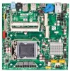
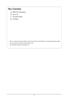
Box Contents, MSH61PI Motherboard Layout, Hardware Installation
 |
View all Gigabyte MSH61DK manuals
Add to My Manuals
Save this manual to your list of manuals |
Page 9 highlights
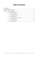
Table of Contents Box Contents...4 MSH61PI Motherboard Layout 5 Chapter 1 Hardware Installation 7 1-1 Installation Precautions 7 1-2 Product Specifications 8 1-3-2 Installing the CPU Cooler 11 1-4 Installing the Memory 12 1-4-1 Dual Channel Memory Configuration 12 1-4-2 Installing a Memory 13 1-5 Back Panel Connectors 14 1-6 Internal Connectors 16 - 3 -
-
 1
1 -
2
-
3
-
 4
4 -
 5
5 -
 6
6 -
 7
7 -
 8
8 -
 9
9 -
 10
10 -
 11
11 -
 12
12 -
 13
13 -
 14
14 -
15
-
16
-
17
-
18
-
19
-
20
-
21
-
22
-
23
-
24
-
25
-
26
-
27
-
28
-
29
-
30
-
31
-
32
-
33
-
34
-
35
-
36
-
37
-
38
-
39
-
40
-
41
-
42
-
43
-
44
-
45
-
46
-
47
-
48
-
49
-
50
-
51
-
52
-
53
-
54
-
55
-
56
-
57
-
58
-
59
-
60
-
61
-
62
-
63
 |
 |

- 3 -
Table of Contents
Box Contents
...................................................................................................................
4
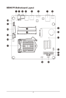
MSH61PI Motherboard Layout
........................................................................................
5
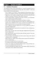
Chapter 1 Hardware Installation
.....................................................................................
7
1-1
Installation Precautions
....................................................................................
7
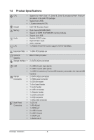
1-2
Product Specifications
......................................................................................
8
1-3-2
Installing the CPU Cooler
.......................................................................................
11
1-4
Installing the Memory
.....................................................................................
12
1-4-1
Dual Channel Memory Configuration
.....................................................................
12
1-4-2
Installing a Memory
...............................................................................................
13
1-5
Back Panel Connectors
..................................................................................
14
1-6
Internal Connectors
........................................................................................
16