Gigabyte X299-WU8 User Manual - Page 31
LED_C1/LED_C2 RGB RGBW LED Strip Headers, SATA3 0/1/2/3/4/5/6/7 SATA 6Gb/s Connectors
 |
View all Gigabyte X299-WU8 manuals
Add to My Manuals
Save this manual to your list of manuals |
Page 31 highlights
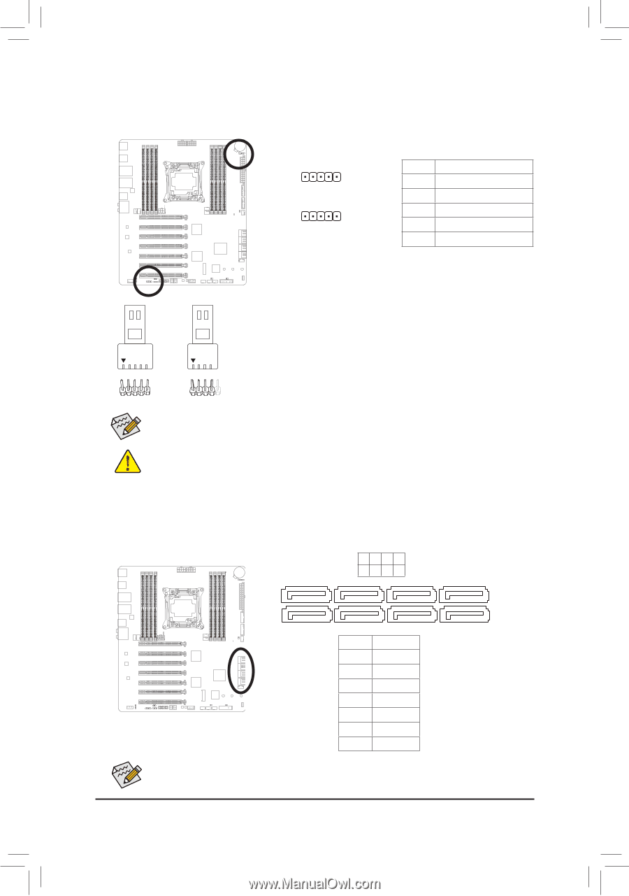
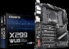
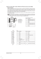
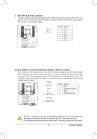
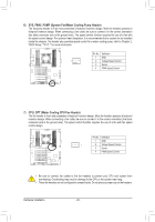
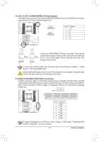
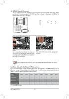
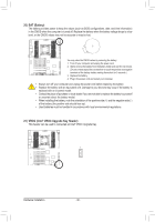
B_ S _S _ B_ S _S _ _ _B _ 12) LED_C1/LED_C2 (RGB (RGBW) LED Strip Headers) The headers can be used to connect a standard 5050 RGB (RGBW) LED strip (12V/G/R/B/W), with maximum power rating of 2A (12V) and maximum length of 2m. LED_C2 _ 1 LED_C1 _ 1 Pin No. 1 2 3 4 5 Definition 12V G R B W RGBW LED Strip RGB LED Strip Connect your RGB (RGBW) LED strip to the header. The power pin (marked with a triangle on the plug) of the LED strip must be connected to Pin 1 (12V) of this header. Incorrect connection may lead to the damage of the LED strip. 1 1 12V 12V B_ F_USB3 B_ For how to turn on/off the lights of the LED strip, refer to the instructions in Chapter 5, "Unique Features," "AUPSPB Before installing C0_eBnter\RGB Fusion." the devices, bBe_sure to turn off the F_USB3 devices and your computer. Unplug the power B_ cord from theUpSoBw0_eBr outlet to prevent damage to the devices. 13) SATA3 0/1/2/3/4/5/6/7 (SATA 6Gb/s Connectors) The SATA connectors conform to SATA 6Gb/s standard and are compatible with SATA 3Gb/s and SATA 1.5Gb/s standard. Each SATA connector supports a single SATA device. The Intel® Chipset supports RAID 0, RAID 1, RAID 5, and RAID 10. Refer to Chapter 3, "Configuring a RAID Set," for instructions on configuring a RAID array. 7531 SATA3 6 4 2 0 7 1 7 1 Pin No. 1 2 3 4 5 6 7 Definition GND TXP TXN GND RXN RXP GND To enable hot-plugging for the SATA ports, refer to Chapter 2, "BIOS Setup," "Peripherals\SATA And RST Configuration," for more information. - 31 - Hardware Installation DEBUG PORT DEBUG PORT DEBUG PORT DEBUG PORT DEBUG PORT DEBUG PORT DEBUG PORT DEBUG PORT
-
 1
1 -
2
-
3
-
4
-
5
-
6
-
7
-
8
-
9
-
10
-
11
-
12
-
13
-
14
-
15
-
16
-
17
-
18
-
19
-
20
-
21
-
22
-
23
-
24
-
25
-
 26
26 -
 27
27 -
 28
28 -
 29
29 -
 30
30 -
 31
31 -
 32
32 -
 33
33 -
 34
34 -
 35
35 -
 36
36 -
37
-
38
-
39
-
40
-
41
-
42
-
43
-
44
-
45
-
46
-
47
-
48
-
49
-
50
-
51
-
52
-
53
-
54
-
55
-
56
-
57
-
58
-
59
-
60
-
61
-
62
-
63
-
64
-
65
-
66
-
67
-
68
-
69
-
70
-
71
-
72
-
73
-
74
-
75
-
76
-
77
-
78
-
79
-
80
-
81
-
82
-
83
-
84
-
85
-
86
-
87
-
88
-
89
-
90
-
91
-
92
-
93
-
94
-
95
-
96
-
97
-
98
-
99
-
100
-
101
-
102
-
103
-
104
-
105
-
106
-
107
-
108
-
109
-
110
-
111
-
112
-
113
-
114
-
115
-
116
-
117
-
118
-
119
-
120
-
121
-
122
-
123
-
124
-
125
-
126
-
127
-
128
-
129
-
130
-
131
-
132
-
133
-
134
-
135
-
136
 |
 |