Gigabyte X299X AORUS XTREME WATER User Manual - Page 22
Back Panel Connectors, USB 2.0/1.1 Port, SMA Antenna Connectors 2T2R, Thunderbolt
 |
View all Gigabyte X299X AORUS XTREME WATER manuals
Add to My Manuals
Save this manual to your list of manuals |
Page 22 highlights
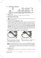
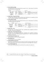
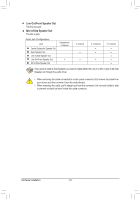
1-7 Back Panel Connectors USB 2.0/1.1 Port The USB port supports the USB 2.0/1.1 specification. Use this port for USB devices. SMA Antenna Connectors (2T2R) Use this connector to connect an antenna. Tighten the antenna cables to the antenna connectors and then move the antenna to a place where the signal is good. Thunderbolt™ 3 Connector (USB Type-C™ Port) The connector supports standard DisplayPort and Thunderbolt™ video outputs. You can connect a standard DisplayPort/Thunderbolt™ monitor to this connector with an adapter. The Thunderbolt™ connector can daisy chain up to six Thunderbolt™ devices. Because of the limited I/O resources of the PC architecture, the number of Thunderbolt™ devices that can be used is dependent on the number of the PCI Express devices being installed. You can adjust the Thunderbolt™ settings under Setting\IO Ports\Thunderbolt(TM) Configuration in BIOS Setup. The maximum supported resolution is 4096x2304@60 Hz when using a DisplayPort monitor, but the actual resolutions supported are dependent on the monitor being used. Also, the connector is reversible and supports the USB 3.2 Gen 2 specification and is compatible to the USB 3.2 Gen 1 and USB 2.0 specification. You can use this port for USB devices, too. Follow the steps below to install the DisplayPort or Thunderbolt™ devices: Step 1: Connect your DisplayPort cable or Mini-DisplayPort cable (purchased separately) from the graphics card to the DisplayPort In port on the back panel. Step 2: Then connect the DisplayPort or Thunderbolt™ devices to Thunderbolt™ 3 connector to complete. Note: For DisplayPort or Thunderbolt™ monitor(s), if you connect the DisplayPort/Mini- DisplayPort cable to the upper DisplayPort In port, you must connect the monitor's cable to the first Thunderbolt™ 3 connector (the one near the DisplayPort In port). If you connect the cable to the lower DisplayPort In port, you must connect the monitor's cable to the second Thunderbolt™ 3 connector (the one near the RJ-45 LAN port). DisplayPort In port The DisplayPort In port offers video outputs to the motherboard. Refer to the Thunderbolt™ 3 Connector for more information. Hardware Installation - 22 -
-
 1
1 -
2
-
3
-
4
-
5
-
6
-
7
-
8
-
9
-
10
-
11
-
12
-
13
-
14
-
15
-
16
-
 17
17 -
 18
18 -
 19
19 -
 20
20 -
 21
21 -
 22
22 -
 23
23 -
 24
24 -
 25
25 -
 26
26 -
 27
27 -
28
-
29
-
30
-
31
-
32
-
33
-
34
-
35
-
36
-
37
-
38
-
39
-
40
-
41
-
42
-
43
-
44
-
45
-
46
-
47
-
48
-
49
-
50
-
51
-
52
-
53
-
54
-
55
-
56
-
57
-
58
-
59
-
60
-
61
-
62
-
63
-
64
-
65
-
66
-
67
-
68
-
69
-
70
-
71
-
72
-
73
-
74
-
75
-
76
-
77
-
78
-
79
-
80
-
81
-
82
-
83
-
84
-
85
-
86
-
87
-
88
-
89
-
90
-
91
-
92
-
93
-
94
-
95
-
96
-
97
-
98
-
99
-
100
-
101
-
102
-
103
-
104
-
105
-
106
-
107
-
108
-
109
-
110
-
111
-
112
-
113
-
114
-
115
-
116
-
117
-
118
-
119
-
120
-
121
-
122
-
123
-
124
-
125
-
126
-
127
-
128
-
129
-
130
-
131
-
132
-
133
-
134
-
135
-
136
 |
 |
