Gigabyte X299X AORUS XTREME WATER User Manual - Page 32
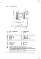
EC_TEMP1/EC_TEMP2 Temperature Sensor Headers, LED_C1/LED_C2 RGB LED Strip Headers, Features
 |
View all Gigabyte X299X AORUS XTREME WATER manuals
Add to My Manuals
Save this manual to your list of manuals |
Page 32 highlights
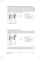
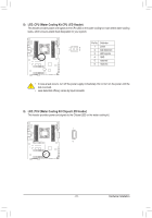
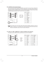
10) EC_TEMP1/EC_TEMP2 (Temperature Sensor Headers) Connect the thermistor cables to the headers for temperature detection. EC_TEMP1 EC_TEMP2 Pin No. Definition 1 1 SENSOR IN 2 GND 11) LED_C1/LED_C2 (RGB LED Strip Headers) The headers can be used to connect a standard 5050 RGB LED strip (12V/G/R/B), with maximum power rating of 2A (12V) and maximum length of 2m. DEBUG PORT DEBUG PORT 1 LED_C1 1 LED_C2 Pin No. 1 2 3 4 Definition 12V G R B Connect one end of the RGB LED strip extension cable to the header and the other end to your RGB LED strip. The black wire (marked B R G 12V B R G 12V with a triangle on the plug) of the extension cable must be connected to Pin 1 (12V) of this header. The 12V pin (marked with an arrow) on B R G 12V B R G 12V RGB LED Strip the other end of the extension cable must be lined up with the 12V of the LED strip. Be careful with the connection orientation of the LED 1 strip; incorrect connection may lead to the damage of the LED strip. 12V For how to turn on/off the lights of the LED strip, refer to the instructions on in Chapter 5, "Unique Features," "APP Center\RGB Fusion." Before installing the devices, be sure to turn off the devices and your computer. Unplug the power cord from the power outlet to prevent damage to the devices. Hardware Installation - 32 -
-
 1
1 -
2
-
3
-
4
-
5
-
6
-
7
-
8
-
9
-
10
-
11
-
12
-
13
-
14
-
15
-
16
-
17
-
18
-
19
-
20
-
21
-
22
-
23
-
24
-
25
-
26
-
 27
27 -
 28
28 -
 29
29 -
 30
30 -
 31
31 -
 32
32 -
 33
33 -
 34
34 -
 35
35 -
 36
36 -
 37
37 -
38
-
39
-
40
-
41
-
42
-
43
-
44
-
45
-
46
-
47
-
48
-
49
-
50
-
51
-
52
-
53
-
54
-
55
-
56
-
57
-
58
-
59
-
60
-
61
-
62
-
63
-
64
-
65
-
66
-
67
-
68
-
69
-
70
-
71
-
72
-
73
-
74
-
75
-
76
-
77
-
78
-
79
-
80
-
81
-
82
-
83
-
84
-
85
-
86
-
87
-
88
-
89
-
90
-
91
-
92
-
93
-
94
-
95
-
96
-
97
-
98
-
99
-
100
-
101
-
102
-
103
-
104
-
105
-
106
-
107
-
108
-
109
-
110
-
111
-
112
-
113
-
114
-
115
-
116
-
117
-
118
-
119
-
120
-
121
-
122
-
123
-
124
-
125
-
126
-
127
-
128
-
129
-
130
-
131
-
132
-
133
-
134
-
135
-
136
 |
 |
