Harman Kardon AVR 350 Owners Manual - Page 26
Video 1 Source, Video 2 Source, Video 3 Source, Video 4 Source
 |
View all Harman Kardon AVR 350 manuals
Add to My Manuals
Save this manual to your list of manuals |
Page 26 highlights
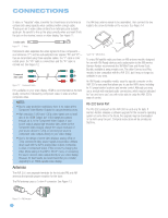
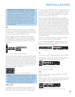
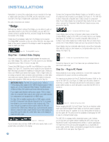
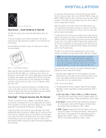
INSTALLATION NOTE: The AVR 350 is equipped with a total of eight digital audio inputs, not including the HDMI inputs: six on the rear panel (Coaxial 1, 2 and 3, Optical 1, 2 and 3) and two on the front panel (Coaxial 4 and Optical 4). However, there are a total of nine sources that may be connected to devices that have digital audio outputs. We recommend certain digital audio connections simply because, as reflected in Table A1 of the Appendix, those digital audio inputs are assigned to those sources by default at the factory. But any digital audio input (except HDMI) may be reassigned to any source. Since you may not be using all nine source inputs, you may reassign a digital audio input that is recommended for a source you aren't using to another device. Table 2 is a guide; you may need to make adjustments to fit your system. Video 1 Source Since this source includes audio and video recording output jacks, it is best suited to a video recorder, such as your VCR or DVR/PVR. You may connect a Harman Kardon DMC 250 or DMC 1000 digital media center to the Video 1 source for easy programming of the remote control. However, if one of the HDMI inputs is available, use it and follow the directions in Step Eight to program the remote. Referring to Table 2, connect your recorder to the Video 1 Analog Audio inputs and outputs and to any available coaxial or optical digital audio input (and corresponding digital audio output). See Figure 20. Use either the Video 1 S-video or composite video input and output if you wish to make recordings. If you don't plan on recording, you may use the Component Video 2 inputs. the Component Video 3 inputs. Otherwise, connect the set-top box's S-video or composite video output to the matching Video 2 video input. See Figure 21. Figure 21 - Video 2 A/V, Digital Audio and Component Video Inputs Video 3 Source The Video 3 source is used for playback only. The remote control is programmed to operate a TV, but you may connect any audio/video source device to the Video 3 inputs and use the device's own remote to control it. If you receive your television programming using your TV with an antenna or direct cable connection, connect the analog audio outputs (if available on your TV) to the Video 3 Analog Audio inputs. See Figure 22. Do not connect any video output on the television set to any video input on the receiver. See Step Five for information on connecting the receiver's video monitor outputs to the TV. NOTE: You may connect any video source other than a display device to the Video 3 S-video or composite video inputs. Figure 20 - Video 1 A/V Inputs and Outputs, and Digital Audio Inputs and Outputs Remember to connect the audio and video output jacks on your recorder to the Video 1 or digital audio input jacks on the AVR, and the audio and video input jacks on your recorder to the Video 1 or digital audio output jacks on the AVR. NOTE: It isn't possible to make recordings using component video or HDMI connections. Keep this in mind as you connect other source devices that you may wish to make recordings from. Video 2 Source The Video 2 source is used only for playback. The AVR 350 remote control is programmed to operate many brands and models of cable and satellite television devices, and we recommend connecting your cable or satellite set-top box to this source. Referring to Table 2, connect your set-top box to the Video 2 Analog Audio inputs and to the Optical 1 Digital Audio input. If possible, use 26 Figure 22 - Video 3 A/V Inputs Video 4 Source The Video 4 source is used only for playback. It is also generally reserved for components that are only temporarily connected to the receiver, such as cameras and game consoles. When not in use, you may place the supplied covers over the front-panel Video 4 jacks for a cleaner appearance. Simply snap the covers in place. When you wish to use the jacks, gently press on the left side of each cover to pivot it out for removal. Referring to Table 2, connect your camera or game console to the Video 4 Analog Audio inputs and to either the Coaxial 4 or Optical 4 digital audio input. Connect the component's S-video or composite video output to the matching Video 4 video input. See Figure 23. Figure 23 - Video 4 A/V and Digital Audio Inputs NOTE: The Video 4 Input Selector on the remote may be programmed to operate a television or video display only.
-
 1
1 -
2
-
3
-
4
-
5
-
6
-
7
-
8
-
9
-
10
-
11
-
12
-
13
-
14
-
15
-
16
-
17
-
18
-
19
-
20
-
 21
21 -
 22
22 -
 23
23 -
 24
24 -
 25
25 -
 26
26 -
 27
27 -
 28
28 -
 29
29 -
 30
30 -
 31
31 -
32
-
33
-
34
-
35
-
36
-
37
-
38
-
39
-
40
-
41
-
42
-
43
-
44
-
45
-
46
-
47
-
48
-
49
-
50
-
51
-
52
-
53
-
54
-
55
-
56
-
57
-
58
-
59
-
60
-
61
-
62
-
63
-
64
-
65
-
66
-
67
-
68
-
69
-
70
-
71
-
72
-
73
-
74
-
75
-
76
 |
 |
