Harman Kardon AVR 350 Owners Manual - Page 28
Bridge
 |
View all Harman Kardon AVR 350 manuals
Add to My Manuals
Save this manual to your list of manuals |
Page 28 highlights
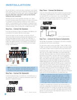
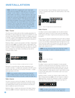
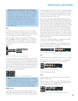
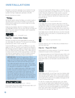
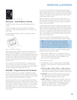
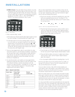
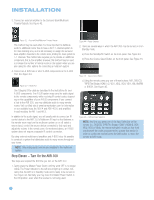
INSTALLATION Remember to connect the output jacks on your recorder to the Tape or digital audio input jacks on the AVR, and the input jacks on your recorder to the Tape or digital audio output jacks on the AVR. No video connections are needed. TheBridgeTM With Harman Kardon's optional The Bridge, you can listen to audio or view videos stored on your iPod (not included), use your AVR 350 remote control to operate the iPod, and even charge the iPod while it's docked in The Bridge. Simply plug the proprietary cable from The Bridge into the special The Bridge/DMP connector on the rear of the AVR 350. See Figure 29. Refer to the owner's manual for The Bridge to select the appropriate insert to match your iPod. Figure 29 - The Bridge/DMP Connector Step Five - Connect Video Display Only video connections should be made between the receiver and your video display (TV), unless your TV is the source for your television programming (see Video 3 Source on page 26). Connect the HDMI Output on the AVR to an HDMI input on your video display. See Figure 30. Consult the owner's guide for your television to learn the proper procedure for disabling or muting the audio. Unless you have a non-HDMI source device that outputs 1080i or higher video via an analog component video connection (see note below), no other video connections are required, thanks to the AVR 350's ability to transcode analog video signals to HDMI, and you may proceed to Step Six. IMPORTANT NOTE: The AVR 350 cannot convert 1080i or 1080p analog video signals to the HDMI format and outputs 1080i signals, as is, to the Component Video Outputs. This affects users of Microsoft Xbox 360 systems and some older set-top boxes. If your digital cable television set-top box outputs 1080i or higher video via component video outputs only contact your cable operator for a replacement unit equipped with an HDM output. For Xbox 360 or satellite receivers with no HDMI output, connect the AVR's Component Video Monitor Outputs to the TV, or change the settings on your source device so that it outputs only 720p video through its component video outputs, which the AVR can convert to the HDMI format. Although you could connect the source device's component video outputs directly to your video display, you would then have to select the correct video input on the display to match the AVR's input. Figure 30 - HDMI Output If your television does not have HDMI or DVI video inputs, make a component video connection to the display. Connect the Component Video Monitor Outputs on the AVR to one set of component video inputs on your display. See Figure 31. The AVR 350 is able to transcode composite and S-video sources to component video. If your video display has component video inputs, then you need only to connect the Component Video Monitor Outputs and you may proceed to Step Six. Figure 31 - Component Video Monitor Outputs If your display does not have component video inputs, connect the S-video Monitor output on the AVR to an S-video input on your display. See Figure 32. The AVR 350 converts composite video sources to S-video. If your video display has S-video inputs, then you need only to connect the S-Video Monitor Output and you may proceed to Step Six. If your display only has composite video inputs, connect the Composite Video Monitor output on the receiver to a composite video input on the display. See Figure 32. Figure 32 - S-Video and Composite Video Monitor Outputs Consult the manual for your TV to make sure you understand how to select each video input. Step Six - Plug in AC Power Having made all of your wiring connections, it is now time to plug each component's AC power cord into a working outlet. You may plug one device into the AC Switched Accessory Outlet on the rear of the AVR 350. See Figure 33. Make sure this device draws no more than 50 watts. The device should have its mechanical or master power switch turned on, and it will power on any time the AVR 350 is turned on. Figure 33 - Switched AC Accessory Outlet Before plugging the AVR 350's AC Power Cord into an electrical outlet, make sure that the Master Power Switch on the front panel is popped out so that the word OFF appears on its top. Gently press the button to turn the switch off. This will prevent the possibility of damaging the AVR in case of a transient power surge. The AVR 350 is equipped with a detachable power cord. It allows you to fully wire your system before installing the AVR, which may be required for some in-wall entertainment centers or custom applications. The male end of the cord should be plugged into an unswitched AC power outlet, and the female end should be plugged into the receptacle on the AVR 350's rear panel. See Figure 34. 28 28
-
 1
1 -
2
-
3
-
4
-
5
-
6
-
7
-
8
-
9
-
10
-
11
-
12
-
13
-
14
-
15
-
16
-
17
-
18
-
19
-
20
-
21
-
22
-
 23
23 -
 24
24 -
 25
25 -
 26
26 -
 27
27 -
 28
28 -
 29
29 -
 30
30 -
 31
31 -
 32
32 -
 33
33 -
34
-
35
-
36
-
37
-
38
-
39
-
40
-
41
-
42
-
43
-
44
-
45
-
46
-
47
-
48
-
49
-
50
-
51
-
52
-
53
-
54
-
55
-
56
-
57
-
58
-
59
-
60
-
61
-
62
-
63
-
64
-
65
-
66
-
67
-
68
-
69
-
70
-
71
-
72
-
73
-
74
-
75
-
76
 |
 |
