Harman Kardon AVR 350 Owners Manual - Page 32
Step Eleven - Turn On the AVR 350
 |
View all Harman Kardon AVR 350 manuals
Add to My Manuals
Save this manual to your list of manuals |
Page 32 highlights
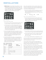
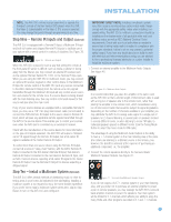
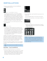
INSTALLATION 3. Connect an external amplifier to the Surround Back/Multiroom Preamp Outputs. See Figure 42. Figure 42 - Surround Back/Multiroom Preamp Outputs This method may be used when it is more important to distribute audio to additional rooms than to have a full 7.1-channel system in the main listening area, as it is still necessary to assign the surround back amplifier channels to the remote zone, limiting the main system to 5.1 channels. This method also requires you to provide an additional component, that is, the amplifier. However, this method may be used to increase the number of remote rooms in the system when you are also using the other options for connecting a multiroom system. 4. Connect an A-BUS hub or other A-BUS components to the A-BUS Port. See Figure 43. Figure 43 - A-BUS Port Use Category 5/5e cable as described in the instructions for your A-BUS components. The A-BUS system may carry the audio signal to the remote components, while receiving IR control codes, depending on the capabilities of your A-BUS components. If you connect a hub to the AVR 350, you may distribute audio to many remote rooms. Visit our Web site at www.harmankardon.com for information on our available hubs, the ABH 4 and ABH 4000, and amplified in-wall modules, the AB 1 and AB 2. In addition to the audio signal, you will usually wish to connect an IR control device to the AVR 350's Multiroom IR Input so that listeners in the remote room may turn the multiroom system on or off, select a source input, control the source device connected to that input and adjust the volume in the remote zone. As mentioned above, an A-BUS system does not require a separate IR control connection. By using external multichannel amplifiers and A-BUS hubs, it's possible to construct a system that distributes audio to many rooms throughout your home. NOTE: Only analog audio sources are available to the multiroom system. Step Eleven - Turn On the AVR 350 Two steps are required the first time you turn on the AVR 350. 1. Gently press the Master Power Switch until the word OFF is no longer visible. The Power Indicator to the left should light up in amber, indicating that the AVR is in Standby mode and is ready to be turned on. See Figure 44. Normally, you may leave the Master Power Switch in the ON position, even when the receiver is not being used. Figure 44 - Power Switches 2. There are several ways in which the AVR 350 may be turned on from Standby mode. a) Press the Standby/On Switch on the front panel. See Figure 44. b) Press the Source Select Button on the front panel. See Figure 45. Figure 45 - Source Select Button c) Using the remote, press any one of these buttons: AVR, DVD/CD, TAPE/The Bridge, HDMI 1/2, VID1, VID2, VID3, VID4, XM, AM/FM or 6/8CH. See Figure 46. Figure 46 - AVR and Input Selectors NOTE: Any time you press one of the Input Selectors on the remote (i.e., DVD/CD, TAPE/The Bridge, HDMI 1/HDMI 2, VID1, VID2, VID3 or VID4), the remote will switch modes so that it will only transmit the codes programmed to operate that device. In order to control the receiver, press the AVR button to return the remote to AVR mode. 32 32
-
 1
1 -
2
-
3
-
4
-
5
-
6
-
7
-
8
-
9
-
10
-
11
-
12
-
13
-
14
-
15
-
16
-
17
-
18
-
19
-
20
-
21
-
22
-
23
-
24
-
25
-
26
-
 27
27 -
 28
28 -
 29
29 -
 30
30 -
 31
31 -
 32
32 -
 33
33 -
 34
34 -
 35
35 -
 36
36 -
 37
37 -
38
-
39
-
40
-
41
-
42
-
43
-
44
-
45
-
46
-
47
-
48
-
49
-
50
-
51
-
52
-
53
-
54
-
55
-
56
-
57
-
58
-
59
-
60
-
61
-
62
-
63
-
64
-
65
-
66
-
67
-
68
-
69
-
70
-
71
-
72
-
73
-
74
-
75
-
76
 |
 |
