Harman Kardon AVR 635 Owners Manual - Page 21
Title, Componentin - setup
 |
View all Harman Kardon AVR 635 manuals
Add to My Manuals
Save this manual to your list of manuals |
Page 21 highlights
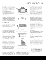
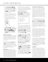
SYSTEM CONFIGURATION 49 47 45 43 48 46 44 42 alter a setting. The configuration settin3gs5for 3sp7eake3r9 41 the next letter, and continue until the desired name is "size" and crossover points are set onc3e4and3a6pplie3d8 40 ente3re7d, up41to a4m7axim5u1m of 14 characters. Press to all inputs. 33 26 25 When using the full-OSD system to m3ak2e the27setu2p 4 adjustments, press the OSD Button 31 on2c8e so23 37 36 the S3e6t Bu4t0ton 4q6 spyrostce3ems5s.me3m9ory4a5nd to50enter the input name into the to4p9roceed with the configuration 35 34 38 44 48 that the MASTER MENU (Figure310) ap2pe9ars.2T2he 34 If yo3ur3system in4cl3udes any sources that are equipped SlineE.cTPurrUseosPrs wthmilelebSneuent(eFBxigututttroeont2he)q wIillNaa/pnpdOetahU22re89ToInSNth33Ee/10TsOcUrUe22ePT10n. 33 with3Y2/Pr/Pb com4p2onent video outputs, the AVR 635 32 is ab3le1to switch them to send the proper signals to your video display. Each of the two Component Press the ‹/› Navigation Button o until the Video Inputs cd may be assigned to any source desired input name appears in the highlighted video, for added system flexibility. The default setting is for as well as being indicated in the front-panel Input Indicators !. When you are scrolling through the the Component Video 1 Jacks c to be assigned to the DVD and 6/8-Channel Direct inputs, with the list of available inputs, you will hear a slight click from Component Video 2 Jacks d assigned to all other time to time. This is normal, as it is caused by the inputs. If your system does not include component relay that is used to switch between the two video at this time, or if you do not need to change Component Video inputs. these defaults, press the ¤ Navigation Button o to go to the next setting. * IN/OUT SETUP * → SOURCE : VIDEO 1 TITLE: COMPONENT IN:COMP V 1 DIGITAL IN :ANALOG COAXIAL 4 :IN OUT VIDEO 4 :IN OUT VIDEO CONV :OFF ON V-CONV PORT :AUTO BACK TO MASTER MENU Figure 2 When one of the four Video inputs is selected as the source, you have the option of renaming the input as it appears in the on-screen and front panel messages. This is helpful if you have more than one VCR, if you wish to associate a specific product brand name with the input, or to simply enter any name that will help you to remember which source is being selected. To change the input name, press the ⁄/¤ Navigation Button o on the remote so that the cursor is pointing to TITLE. Next, press and hold the Set Button q for a few seconds until a flashing box appears to the right of the colon. Immediately release the Set Button q, as you are now ready to enter the device name. Press the ⁄/¤ Navigation Button o and note that a complete set of alphanumeric characters will appear with the start of the alphabet in capital letters followed by the lowercase letters and then numbers and symbols. When you press the ¤ Navigation Button o, a series of symbols and numbers will appear, followed by a reverse list of the alphabet in lowercase letters. Press the button either way until the first letter of the desired name appears. If you wish to enter a blank space as the first character, press the › Navigation Button o. When the desired character appears, press the › Navigation Button o and repeat the process for To change the Component Video assignment, first make certain that the cursor is pointing to the COMPONENT IN line on the menu screen, and then press the ‹/› Navigation Button o until you see the desired input in the highlighted video. The clicking noise that you will hear when the component video inputs are switched is normal, due to the relay used to ensure proper isolation between the two inputs. When the desired component input has been selected, press the ¤ Navigation Button o to go to the next setting. If you wish to associate one of the digital inputs with the selected input source or change the default digital input selection, press the ¤ Navigation Button o on the remote while the IN/OUT SETUP menu (Figure 2) is on the screen, and the on-screen cursor will drop down to the DIGITAL IN line. Press the ‹/› Navigation Button o until the name of the desired digital input appears. To return to the analog input, press the button until the word ANALOG appears. When configuring the digital input for a source device such as a digital cable box or other set-top tuner product with a digital audio output where you have connected both the digital and analog outputs of the source to the AVR, select the appropriate digital input on this menu. The digital source will become the default, and the AVR will always look there first to see whether a signal is present. However, if the digital data stream is interrupted for any reason, the AVR will automatically switch to the analog connection as a backup. This is particularly useful when configuring the connection for digital set-top boxes, where some channels feature digital sound, but others do not. To change the digital input at any time using the discrete function buttons and the semi-OSD system, press the Digital Select Button p on the remote. Within 5 seconds, make your input selection using the ⁄/¤ Navigation Button o until the desired digital or analog input is shown in the Upper Display Line # and in the lower line of the on-screen display. An exclusive Harman Kardon feature is the ability to switch front-panel coaxial digital audio and analog audio/video jacks from their normal use as inputs to output connections so that portable recording devices may easily be connected. On the AVR 635, the Coaxial 4 Digital Jack M is normally an input, but this may also be switched to a digital output for use with CD-R/RW decks, MD recorders or other digital recorders. To change the jack to an output, press the ⁄/¤ Navigation Button o while the IN/OUT SETUP menu is on the screen until the cursor is next to COAXIAL 4. Then press the ‹/› Navigation Button o so that OUT is highlighted. The Input/Output Status Indicator L will turn red, indicating that the jack is now a record output. NOTE: A signal will be sent to this jack only when the input selected for use by the AVR 635 is digital. Digital signals will be passed through regardless of their format, and which digital input (optical or coax) they are fed from. However, analog signals are not converted to digital, and the format of the signal (e.g., PCM, Dolby Digital or DTS) may not be changed. The front-panel analog Video 4 Inputs N are normally set as an input for use with camcorders, video games and other portable audio/video products, but they may be switched to an output for connection to audio/video recorders. To temporarily switch them to outputs, you must first be at the IN/OUT SETUP menu. Press the ¤ Navigation Button o until the on-screen cursor is pointing to the VIDEO 4 line. Press the › Navigation Button o so that the word OUT is highlighted. The Input/Output Status Indicator L between the Sand composite video jacks will turn red, indicating that the analog Video 4 jacks are now record outputs. Selection of the front-panel jacks as an output will remain effective as long as the AVR 635 is on. Once the unit is turned off, the jacks will revert to their normal use as an input when the unit is turned on again. The AVR 635 uses high-quality video decoding circuitry that makes it possible to convert standard (composite) or S-video signals from their original form to separate component analog outputs that carry the receiver's OSD menus and messages with no loss in quality. This enables you to simplify connections to a digital video SYSTEM CONFIGURATION 21
-
 1
1 -
2
-
3
-
4
-
5
-
6
-
7
-
8
-
9
-
10
-
11
-
12
-
13
-
14
-
15
-
 16
16 -
 17
17 -
 18
18 -
 19
19 -
 20
20 -
 21
21 -
 22
22 -
 23
23 -
 24
24 -
 25
25 -
 26
26 -
27
-
28
-
29
-
30
-
31
-
32
-
33
-
34
-
35
-
36
-
37
-
38
-
39
-
40
-
41
-
42
-
43
-
44
-
45
-
46
-
47
-
48
-
49
-
50
-
51
-
52
-
53
-
54
-
55
-
56
-
57
-
58
-
59
-
60
 |
 |
