Harman Kardon AVR 635 Owners Manual - Page 22
Audio Setup, Surround Setup - turns of
 |
View all Harman Kardon AVR 635 manuals
Add to My Manuals
Save this manual to your list of manuals |
Page 22 highlights
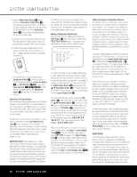
SYSTEM CONFIGURATION display since only one set of component video cables is needed to view all input sources connected to the AVR 635. Conversely, the conversion circuitry may be used to convert component inputs to an S-video or composite video output when a receiver that is capable of displaying a component signal is not available. In most cases you will want to have the conversion circuitry engaged, but in some installations it may be preferable to turn it off. If you prefer the way a video signal looks in its original form, you may turn the video conversion circuitry off by first making certain that the IN/OUT SETUP menu (Figure 2) is on the screen, and then pressing the ⁄/¤ Navigation Button o until the cursor is pointing to VIDEO CONV and then press the ‹/› Navigation Button o so that OFF is shown in highlighted video. This setting is made individually for each input, so be certain to make any desired change for each input source where you wish to turn the conversion circuitry off. Should you wish to return the conversion circuitry to the On position at any time, simply use the steps shown above, but press the ‹/› Navigation Button o so that ON is shown in highlighted video. The final input setting is also individual to each input, and it allows you to set the priority for the video conversion circuitry. In most cases, where only one type of video connection is made between a source device and the AVR you will not need to change this setting, and if all other parameters have been adjusted to meet your system requirements, you may proceed to the next configuration steps by pressing the ⁄/¤ Navigation Button o until the cursor is pointing to BACK TO MASTER MENU and then pressing the Set Button p. In some cases when you wish to set a specific input for the video conversion circuits, a change to the setting here is required. In the Automatic mode, the AVR will scan all video inputs and route the first signal it encounters to the component output. However, in advanced systems, or when more than one video input is connected to the same source, you may want to bypass the automatic selection and manually choose which signal is converted. For example, in some cases both component and standard composite video outputs from a set-top box may be connected to the AVR so that the component signal is fed to a digital video display and the composite signal to a recorder. In this case you would not want the composite signal converted, but rather have the component signal passed through to the main output with the composite. To make this type of system configuration first make certain that the IN/OUT SETUP menu (Figure 2) is on the screen, Next, press the ⁄/¤ Navigation Button o until the cursor is pointing to V-CONV PORT. When the default of AUTO is shown the unit will first look at the CVBS (composite video) input, then to the S-video and Component inputs for the source to be routed to the component outputs. To select a specific output, press the ‹/› Navigation Button o until your desired choice appears in highlighted video. When all needed adjustments have been made, press the ¤ Navigation Button o until the cursor is next to BACK TO MASTER MENU to continue with the system configuration. Audio Setup This menu allows you to configure the tone controls and to turn the upsampling on or off. If you do not wish to change any of those settings at this time, proceed to the next menu screen. However, to make configuration changes to those parameters, make certain that the MASTER MENU is on screen with the cursor pointing to the AUDIO SETUP line, and press the Set Button q. The AUDIO SETUP menu (Figure 3) will appear. * AUDIO SETUP * → TONE :IN OUT BASS :0 TREBLE :0 ADC SAMPLING:48k 96k BACK TO MASTER MENU Figure 3 The first line controls whether or not the bass/treble tone controls are in the signal path. The normal default is for them to be in-line, but if you wish to remove them from the circuit for "flat" response, first make certain that the cursor is pointing to the TONE line on the menu and press the ‹/› Navigation Button o so that OUT is highlighted in reverse video. If you wish to leave the tone controls in the signal path, the amount off boost or cut for bass and treble may be adjusted by pressing the ⁄/¤ Navigation Button o so that the cursor is next to bassor treble depending on which setting you wish to adjust. Next, press the ‹/› Navigation Button o until the desired setting is shown. This menu also includes a setting to turn the unit's upsampling feature on or off. In normal use, this feature is turned off, which means that digital sources are processed at their native sample rate. For example, a 48kHz digital source will be processed at 48kHz. However, the AVR 635 allows you to upsample the incoming 48kHz signals to 96kHz for added resolution. To take advantage of this feature, press the ⁄/¤ Navigation Button o so that the cursor is next to the UPSAMPLING line and press the ‹/› Navigation Button o so that ON is highlighted in reverse video. Note that this feature is only available for the Dolby Pro Logic II-Music, Dolby Pro Logic IIMovie, Dolby Pro Logic and Dolby 3 Stereo modes. When all desired changes have been made on this menu, press the ⁄/¤ Navigation Button o so that the cursor is next to the BACK TO MAIN MENU line; press the Set Button q. Surround Setup The next step is to set the surround mode you wish to use with the input that was previously selected in the IN/OUT SETUP menu. Since surround modes are a matter of personal taste, feel free to select any mode you wish - you may change it later. However, to make it easier to establish the initial parameters for the AVR 635, we suggest Logic 7 (Cinema or Music) for most analog inputs. In the case of inputs such as a CD Player, Tape Deck or Tuner, you may wish to set the mode to Stereo ("Surround off") as they are not typically used with multichannel program material, and it is unlikely that surround-encoded material will be used. Alternatively, the Logic 7 Music mode is a good choice for stereo-only source material. See page 34 for more information on available surround modes. For digital program material, the AVR will always examine the data stream and automatically select a Dolby Digital or DTS mode as applicable. It is easiest to complete the surround setup using the full-OSD on-screen menus. From the MASTER MENU (Figure 1), press the ⁄/¤ Navigation Button o until the cursor is next to the SURROUND SELECT line. Press the Set Button q until the SURROUND SELECT menu (Figure 4) is on the screen. ** SURROUND SELECT ** DOLBY SURROUND DTS LOGIC 7 DSP (SURR) STEREO BACK TO MASTER MENU Figure 4 22 SYSTEM CONFIGURATION
-
 1
1 -
2
-
3
-
4
-
5
-
6
-
7
-
8
-
9
-
10
-
11
-
12
-
13
-
14
-
15
-
16
-
 17
17 -
 18
18 -
 19
19 -
 20
20 -
 21
21 -
 22
22 -
 23
23 -
 24
24 -
 25
25 -
 26
26 -
 27
27 -
28
-
29
-
30
-
31
-
32
-
33
-
34
-
35
-
36
-
37
-
38
-
39
-
40
-
41
-
42
-
43
-
44
-
45
-
46
-
47
-
48
-
49
-
50
-
51
-
52
-
53
-
54
-
55
-
56
-
57
-
58
-
59
-
60
 |
 |
