Harman Kardon CR151 Owners Manual - Page 8
Connections
 |
View all Harman Kardon CR151 manuals
Add to My Manuals
Save this manual to your list of manuals |
Page 8 highlights
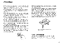
Connections After installing the unit, connect wires according to the diagram on the 8 page. During the connecting operation, make sure that the negative terminal (-) of the battery is disconnected to prevent accidents caused by short circuit. The entire memory may be deleted when the negative terminal (-) of the battery is disconnected for cars equipped with a drive computer or navigation computer. For this type of car, connect the power to the amplifier after connecting operations without disconnecting the negative terminal. Be sure to keep all wires away from hot or moving parts that may damage them. 0 POWER AMP REMOTE wire Connect the POWER AMP REMOTE wire (yellow) to the remote terminal on amplifier or graphic equalizer. 0 POWER ANTENNA wire Connect the POWER ANTENNA wire (blue) to the power antenna relay or the antenna booster. For some models with a window antenna, it is necessary to supply power to the antenna booster. In this case, connect the POWER ANTENNA lead to the antenna booster, or supply power from the accessory circuit. A power antenna without a relay cannot be used. O MEMORY Back Up wire The +12V MEMORY wire (orange) is a positive power input. It should be connected to a circuit which is always on in order to retain the tuner memory. O ILLUMINATION wire This is the power supply wire (white) for lighting the front panel. It can be connected to the dash dimmer control, so that the front panel illumination will be similar to the dash lights. Or, it can be connected to the "+12V SWITCHED" lead, in which case the illumination will be uncontrollable. 7
-
 1
1 -
2
-
 3
3 -
 4
4 -
 5
5 -
 6
6 -
 7
7 -
 8
8 -
 9
9 -
 10
10 -
 11
11 -
 12
12 -
 13
13 -
14
-
15
-
16
-
17
-
18
-
19
-
20
 |
 |
