HealthRider H30x Bike English Manual - Page 8
Attach the Pivot Cover 12 to the Handlebar 5
 |
View all HealthRider H30x Bike manuals
Add to My Manuals
Save this manual to your list of manuals |
Page 8 highlights
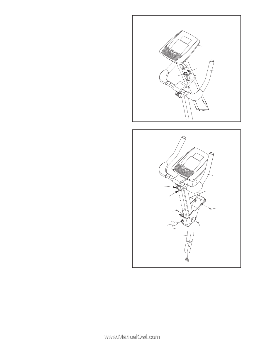
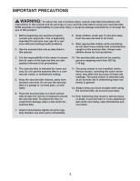
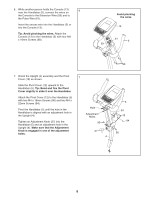
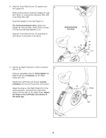
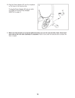
6. While another person holds the Console (13) near the Handlebar (5), connect the wires on 6 the Console to the Extension Wire (59) and to the Pulse Wire (61). Insert the excess wire into the Handlebar (5) or into the Console (13). Tip: Avoid pinching the wires. Attach the Console (13) to the Handlebar (5) with four M4 x 16mm Screws (90). Avoid pinching the wires 13 61 5 59 90 7. Orient the Upright (4) assembly and the Pivot Cover (12) as shown. Slide the Pivot Cover (12) upward to the Handlebar (5). Tip: Bend and flex the Pivot Cover slightly to slide it over the Handlebar. Attach the Pivot Cover (12) to the Handlebar (5) with two M4 x 16mm Screws (90) and two M4 x 22mm Screws (94). Pivot the Handlebar (5) until the hole in the Handlebar is aligned with an adjustment hole in the Upright (4). Tighten an Adjustment Knob (27) into the Handlebar (5) and an adjustment hole in the Upright (4). Make sure that the Adjustment Knob is engaged in one of the adjustment holes. 7 Hole Adjustment Holes 90 27 4 5 94 12 94 90 8
-
 1
1 -
2
-
 3
3 -
 4
4 -
 5
5 -
 6
6 -
 7
7 -
 8
8 -
 9
9 -
 10
10 -
 11
11 -
 12
12 -
 13
13 -
14
-
15
-
16
-
17
-
18
-
19
-
20
-
21
-
22
-
23
-
24
 |
 |