HealthRider H85t Treadmill English Manual - Page 12
Lower the Frame 53 see HOW TO LOWER - treadmill belt
 |
View all HealthRider H85t Treadmill manuals
Add to My Manuals
Save this manual to your list of manuals |
Page 12 highlights
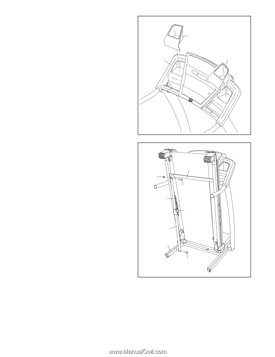
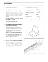
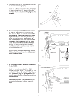
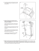
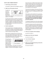
13. If necessary, press the Left Accessory Tray (94) 13 and the Right Accessory Tray (99) into the con- sole assembly. 94 Console Assembly 99 14. Raise the Frame (53) to the position shown. Have a second person hold the Frame until 14 this step is completed. Orient the Storage Latch (50) so that the large barrel and the Latch Knob (51) are in the posi- 53 tions shown. 11 Attach the lower end of the Storage Latch (50) to the bracket on the Base (60) with a 3/8" x 1 3/4" Screw (8). 3 50 Attach the upper end of the Storage Latch (50) to the bracket on the Frame (53) with a 3/8" x 2" Bolt (3) and a 3/8" Locknut (11). Lower the Frame (53) (see HOW TO LOWER THE TREADMILL FOR USE on page 21). 51 Large Barrel 60 8 15. Make sure that all parts are properly tightened before you use the treadmill. If there are sheets of clear plastic on the treadmill decals, remove the plastic. To protect the oor or carpet, place a mat under the treadmill. Note: Extra parts may be included. Keep the included hex keys in a secure place; one of the hex keys is used to adjust the walking belt (see pages 23 and 24). 12
-
 1
1 -
2
-
3
-
4
-
5
-
6
-
 7
7 -
 8
8 -
 9
9 -
 10
10 -
 11
11 -
 12
12 -
 13
13 -
 14
14 -
 15
15 -
 16
16 -
 17
17 -
18
-
19
-
20
-
21
-
22
-
23
-
24
-
25
-
26
-
27
-
28
-
29
-
30
-
31
-
32
 |
 |