HP 10 Plus 2201us HP 10 Plus 2201 Tablet and HP 10 2101 Tablet - Maintenance a - Page 21
Removal and replacement procedures, Back cover
 |
View all HP 10 Plus 2201us manuals
Add to My Manuals
Save this manual to your list of manuals |
Page 21 highlights
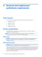
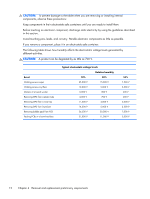
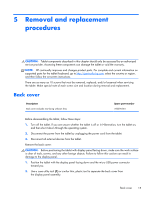
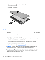
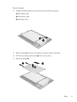
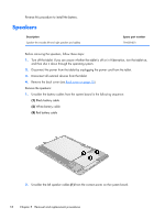
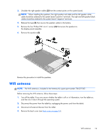
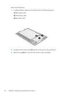
5 Removal and replacement procedures CAUTION: Tablet components described in this chapter should only be accessed by an authorized service provider. Accessing these components can damage the tablet or void the warranty. NOTE: HP continually improves and changes product parts. For complete and current information on supported parts for the tablet/keyboard, go to http://partsurfer.hp.com, select the country or region, and then follow the on-screen instructions. There are as many as 10 screws that must be removed, replaced, and/or loosened when servicing the tablet. Make special note of each screw size and location during removal and replacement. Back cover Description Back cover (includes rear-facing webcam lens) Spare part number 782396-001 Before disassembling the tablet, follow these steps: 1. Turn off the tablet. If you are unsure whether the tablet is off or in Hibernation, turn the tablet on, and then shut it down through the operating system. 2. Disconnect the power from the tablet by unplugging the power cord from the tablet. 3. Disconnect all external devices from the tablet. Remove the back cover: CAUTION: Before positioning the tablet with display panel facing down, make sure the work surface is clear of tools, screws, and any other foreign objects. Failure to follow this caution can result in damage to the display panel. 1. Position the tablet with the display panel facing down and the micro USB power connector toward you. 2. Use a case utility tool (1) or similar thin, plastic tool to separate the back cover from the display panel assembly. Back cover 15
-
 1
1 -
2
-
3
-
4
-
5
-
6
-
7
-
8
-
9
-
10
-
11
-
12
-
13
-
14
-
15
-
 16
16 -
 17
17 -
 18
18 -
 19
19 -
 20
20 -
 21
21 -
 22
22 -
 23
23 -
 24
24 -
 25
25 -
 26
26 -
27
-
28
-
29
-
30
-
31
-
32
-
33
-
34
-
35
-
36
-
37
-
38
-
39
-
40
-
41
-
42
-
43
-
44
-
45
-
46
 |
 |