HP 10 Plus 2201us HP 10 Plus 2201 Tablet and HP 10 2101 Tablet - Maintenance a - Page 40
to which the TouchScreen cable is attached, and then, cable is attached
 |
View all HP 10 Plus 2201us manuals
Add to My Manuals
Save this manual to your list of manuals |
Page 40 highlights
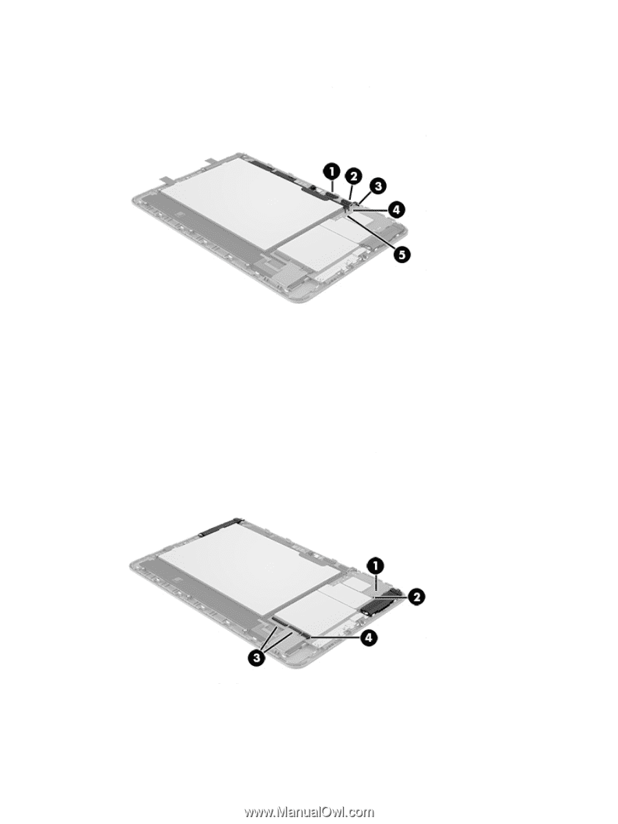
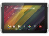
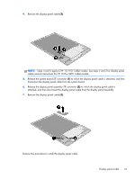
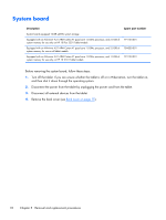
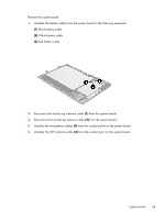
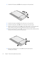
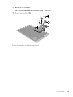
6. Unsolder the Wifi antenna cable (5) from the contact point on the system board. 7. Unsolder the left speaker cables (1) from the contact points on the system board. 8. Unsolder the right speaker cables (2) from the contact points on the system board. 9. Release the system board ZIF connector (3) (varying by tablet model) to which the display panel cable is attached, and then disconnect the display panel cable from the system board. 10. Release the system board ZIF connector (4) to which the TouchScreen cable is attached, and then disconnect the TouchScreen cable from the system board. 11. Remove the six Phillips PM1.6×4.1 screws (1) that secure the system board to the display panel assembly. 34 Chapter 5 Removal and replacement procedures
-
 1
1 -
2
-
3
-
4
-
5
-
6
-
7
-
8
-
9
-
10
-
11
-
12
-
13
-
14
-
15
-
16
-
17
-
18
-
19
-
20
-
21
-
22
-
23
-
24
-
25
-
26
-
27
-
28
-
29
-
30
-
31
-
32
-
33
-
34
-
 35
35 -
 36
36 -
 37
37 -
 38
38 -
 39
39 -
 40
40 -
 41
41 -
 42
42 -
 43
43 -
 44
44 -
 45
45 -
46
 |
 |