HP 14-ac000 Maintenance and Service Guide - Page 42
Bottom cover, Remove the optical drive see
 |
View all HP 14-ac000 manuals
Add to My Manuals
Save this manual to your list of manuals |
Page 42 highlights
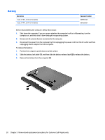
Bottom cover In this section, the first table provides the main spare part number for the top covers/keyboards. The second table provides the country codes. NOTE: All top cover/keyboard spare part kits include a touchpad. Description Top cover with keyboard for use in all black models Top cover with keyboard for use in turbo silver HP Notebook models Top cover with keyboard for use in white silver HP Notebook models Top cover with keyboard for use in purple HP Notebook models Top cover with keyboard for use in blue HP Notebook models Top cover with keyboard for use in red HP Notebook models Spare part number 813513-xxx 813915-xxx 813911-xxx 813913-xxx 813912-xxx 813914-xxx For use in country or region Brazil Canada Czech Republic and Slovakia Denmark, Finland, and Norway France Germany Greece Israel Spare part number -201 -DB1 -FL1 For use in country or region Italy Japan Latin America Spare part number -061 -291 -161 For use in country or region Slovenia South Korea Spain -DH1 Latin America -061 Taiwan -051 -041 -151 -BB1 Netherlands and Europe Portugal Russia Saudi Arabia -B31 -131 -251 -171 Thailand Turkey United Kingdom United States Spare part number -BA1 -AD1 -071 -AB1 -281 -141 -031 -001 Before removing the bottom cover, follow these steps: 1. Shut down the computer. If you are unsure whether the computer is off or in Hibernation, turn the computer on, and then shut it down through the operating system. 2. Disconnect all external devices connected to the computer. 3. Disconnect the power from the computer by first unplugging the power cord from the AC outlet and then unplugging the AC adapter from the computer. 4. Remove the battery (see Battery on page 30). 5. Remove the optical drive (see Optical drive on page 31), if installed. To remove the bottom cover: 1. Position the computer upside down with the front toward you. 2. Remove the 2 broadhead Phillips PM2.0×2.0 screws (1) from the optical drive bay. 34 Chapter 6 Removal and replacement procedures for Authorized Service Provider parts
-
 1
1 -
2
-
3
-
4
-
5
-
6
-
7
-
8
-
9
-
10
-
11
-
12
-
13
-
14
-
15
-
16
-
17
-
18
-
19
-
20
-
21
-
22
-
23
-
24
-
25
-
26
-
27
-
28
-
29
-
30
-
31
-
32
-
33
-
34
-
35
-
36
-
 37
37 -
 38
38 -
 39
39 -
 40
40 -
 41
41 -
 42
42 -
 43
43 -
 44
44 -
 45
45 -
 46
46 -
 47
47 -
48
-
49
-
50
-
51
-
52
-
53
-
54
-
55
-
56
-
57
-
58
-
59
-
60
-
61
-
62
-
63
-
64
-
65
-
66
-
67
-
68
-
69
-
70
-
71
-
72
-
73
-
74
-
75
-
76
-
77
-
78
-
79
-
80
-
81
-
82
-
83
-
84
-
85
-
86
-
87
-
88
-
89
-
90
-
91
-
92
-
93
-
94
-
95
-
96
-
97
-
98
-
99
-
100
-
101
-
102
-
103
-
104
-
105
-
106
-
107
-
108
-
109
-
110
-
111
-
112
-
113
-
114
-
115
-
116
-
117
-
118
-
119
-
120
-
121
-
122
-
123
-
124
-
125
-
126
 |
 |
