HP 14-ac000 Maintenance and Service Guide - Page 43
Remove the 4 Phillips PM2.5×6.0 screws, to separate
 |
View all HP 14-ac000 manuals
Add to My Manuals
Save this manual to your list of manuals |
Page 43 highlights
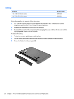
3. Remove the two rubber feet from rear of the bottom of the computer (2) 4. Remove the 4 Phillips PM2.5×6.0 screws (3) from the rear corners of the computer. 5. Remove the 11 Phillips PM2.5×6.0 screws that secure the bottom cover to the computer. 6. Start prying near the optical drive bay (1) and work around to the back (2) and side (3) to separate the bottom cover from computer (1). Component replacement procedures 35
-
 1
1 -
2
-
3
-
4
-
5
-
6
-
7
-
8
-
9
-
10
-
11
-
12
-
13
-
14
-
15
-
16
-
17
-
18
-
19
-
20
-
21
-
22
-
23
-
24
-
25
-
26
-
27
-
28
-
29
-
30
-
31
-
32
-
33
-
34
-
35
-
36
-
37
-
 38
38 -
 39
39 -
 40
40 -
 41
41 -
 42
42 -
 43
43 -
 44
44 -
 45
45 -
 46
46 -
 47
47 -
 48
48 -
49
-
50
-
51
-
52
-
53
-
54
-
55
-
56
-
57
-
58
-
59
-
60
-
61
-
62
-
63
-
64
-
65
-
66
-
67
-
68
-
69
-
70
-
71
-
72
-
73
-
74
-
75
-
76
-
77
-
78
-
79
-
80
-
81
-
82
-
83
-
84
-
85
-
86
-
87
-
88
-
89
-
90
-
91
-
92
-
93
-
94
-
95
-
96
-
97
-
98
-
99
-
100
-
101
-
102
-
103
-
104
-
105
-
106
-
107
-
108
-
109
-
110
-
111
-
112
-
113
-
114
-
115
-
116
-
117
-
118
-
119
-
120
-
121
-
122
-
123
-
124
-
125
-
126
 |
 |

3.
Remove the two rubber feet from rear of the bottom of the computer
(2)
4.
Remove the 4 Phillips PM2.5×6.0 screws
(3)
from the rear corners of the computer.
5.
Remove the 11 Phillips PM2.5×6.0 screws that secure the bottom cover to the computer.
6.
Start prying near the optical drive bay
(1)
and work around to the back
(2)
and side
(3)
to separate the
bottom cover from computer
(1)
.
Component replacement procedures
35