HP 14-ac000 Maintenance and Service Guide - Page 73
Remove the top display hinge, that secure the top hinge to the display enclosure.
 |
View all HP 14-ac000 manuals
Add to My Manuals
Save this manual to your list of manuals |
Page 73 highlights
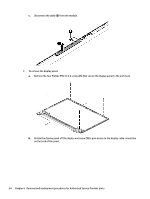
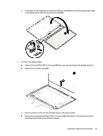
c. On the back of the display panel, release the adhesive strip (2) that secures the display panel cable to the display panel, and then disconnect the cable (3). 4. To remove the display hinges: a. Remove the two Phillips PM2.0×3.0 screws (1) that secure the top hinge to the display enclosure. b. Remove the top display hinge (2). c. Lift the tape that secures the left and right hinges to the enclosure (1). d. Remove the six broadhead Phillips PM2.5×2.0 screws (2) at the bottom of the hinges that secure the left and right hinges to the display enclosure. Component replacement procedures 65
-
 1
1 -
2
-
3
-
4
-
5
-
6
-
7
-
8
-
9
-
10
-
11
-
12
-
13
-
14
-
15
-
16
-
17
-
18
-
19
-
20
-
21
-
22
-
23
-
24
-
25
-
26
-
27
-
28
-
29
-
30
-
31
-
32
-
33
-
34
-
35
-
36
-
37
-
38
-
39
-
40
-
41
-
42
-
43
-
44
-
45
-
46
-
47
-
48
-
49
-
50
-
51
-
52
-
53
-
54
-
55
-
56
-
57
-
58
-
59
-
60
-
61
-
62
-
63
-
64
-
65
-
66
-
67
-
 68
68 -
 69
69 -
 70
70 -
 71
71 -
 72
72 -
 73
73 -
 74
74 -
 75
75 -
 76
76 -
 77
77 -
 78
78 -
79
-
80
-
81
-
82
-
83
-
84
-
85
-
86
-
87
-
88
-
89
-
90
-
91
-
92
-
93
-
94
-
95
-
96
-
97
-
98
-
99
-
100
-
101
-
102
-
103
-
104
-
105
-
106
-
107
-
108
-
109
-
110
-
111
-
112
-
113
-
114
-
115
-
116
-
117
-
118
-
119
-
120
-
121
-
122
-
123
-
124
-
125
-
126
 |
 |

c.
On the back of the display panel, release the adhesive strip
(2)
that secures the display panel cable
to the display panel, and then disconnect the cable
(3)
.
4.
To remove the display hinges:
a.
Remove the two Phillips PM2.0×3.0 screws
(1)
that secure the top hinge to the display enclosure.
b.
Remove the top display hinge
(2)
.
c.
Lift the tape that secures the left and right hinges to the enclosure
(1)
.
d.
Remove the six broadhead Phillips PM2.5×2.0 screws
(2)
at the bottom of the hinges that secure
the left and right hinges to the display enclosure.
Component replacement procedures
65