HP 14-ac000 Maintenance and Service Guide - Page 72
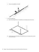
Rotate the display panel, that secure the display panel to the enclosure.
 |
View all HP 14-ac000 manuals
Add to My Manuals
Save this manual to your list of manuals |
Page 72 highlights
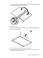
c. Disconnect the cable (2) from the module. 3. To remove the display panel: a. Remove the four Phillips PM2.0×2.4 screws (1) that secure the display panel to the enclosure. b. Rotate the display panel off the display enclosure (1) to gain access to the display cable connection on the back of the panel. 64 Chapter 6 Removal and replacement procedures for Authorized Service Provider parts
-
 1
1 -
2
-
3
-
4
-
5
-
6
-
7
-
8
-
9
-
10
-
11
-
12
-
13
-
14
-
15
-
16
-
17
-
18
-
19
-
20
-
21
-
22
-
23
-
24
-
25
-
26
-
27
-
28
-
29
-
30
-
31
-
32
-
33
-
34
-
35
-
36
-
37
-
38
-
39
-
40
-
41
-
42
-
43
-
44
-
45
-
46
-
47
-
48
-
49
-
50
-
51
-
52
-
53
-
54
-
55
-
56
-
57
-
58
-
59
-
60
-
61
-
62
-
63
-
64
-
65
-
66
-
 67
67 -
 68
68 -
 69
69 -
 70
70 -
 71
71 -
 72
72 -
 73
73 -
 74
74 -
 75
75 -
 76
76 -
 77
77 -
78
-
79
-
80
-
81
-
82
-
83
-
84
-
85
-
86
-
87
-
88
-
89
-
90
-
91
-
92
-
93
-
94
-
95
-
96
-
97
-
98
-
99
-
100
-
101
-
102
-
103
-
104
-
105
-
106
-
107
-
108
-
109
-
110
-
111
-
112
-
113
-
114
-
115
-
116
-
117
-
118
-
119
-
120
-
121
-
122
-
123
-
124
-
125
-
126
 |
 |

c.
Disconnect the cable
(2)
from the module.
3.
To remove the display panel:
a.
Remove the four Phillips PM2.0×2.4 screws
(1)
that secure the display panel to the enclosure.
b.
Rotate the display panel
off
the display enclosure
(1)
to gain access to the display cable connection
on the back of the panel.
64
Chapter 6
Removal and replacement procedures for Authorized Service Provider parts