HP 15-f085wm HP 15 Notebook PC Maintenance and Service Guide - Page 81
Be sure the work surface is clear of all tools, screws, and computer components before
 |
View all HP 15-f085wm manuals
Add to My Manuals
Save this manual to your list of manuals |
Page 81 highlights
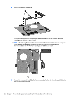
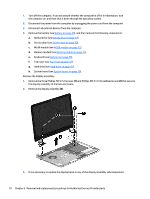
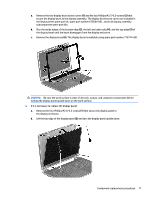
a. Remove the two display bezel screw covers (1) and the two Phillips M2.5×5.0 screws (2) that secure the display bezel to the display assembly. The display bezel screw covers are included in the display bezel spare part kit, spare part number 676644-001, and in all display assembly subcomponent spare part kits. b. Flex the inside edges of the bottom edge (3), the left and right sides (4), and the top edge (5) of the display bezel until the bezel disengages from the display enclosure. c. Remove the display bezel (6). The display bezel is available using spare part number 776774-001. CAUTION: Be sure the work surface is clear of all tools, screws, and computer components before turning the display panel upside down on the work surface. 4. If it is necessary to replace the display panel: a. Remove the four Phillips M2.0×3.5 screws (1) that secure the display panel to the display enclosure. b. Lift the top edge of the display panel (2) and turn the display panel upside down. Component replacement procedures 71
-
 1
1 -
2
-
3
-
4
-
5
-
6
-
7
-
8
-
9
-
10
-
11
-
12
-
13
-
14
-
15
-
16
-
17
-
18
-
19
-
20
-
21
-
22
-
23
-
24
-
25
-
26
-
27
-
28
-
29
-
30
-
31
-
32
-
33
-
34
-
35
-
36
-
37
-
38
-
39
-
40
-
41
-
42
-
43
-
44
-
45
-
46
-
47
-
48
-
49
-
50
-
51
-
52
-
53
-
54
-
55
-
56
-
57
-
58
-
59
-
60
-
61
-
62
-
63
-
64
-
65
-
66
-
67
-
68
-
69
-
70
-
71
-
72
-
73
-
74
-
75
-
 76
76 -
 77
77 -
 78
78 -
 79
79 -
 80
80 -
 81
81 -
 82
82 -
 83
83 -
 84
84 -
 85
85 -
 86
86 -
87
-
88
-
89
-
90
-
91
-
92
-
93
-
94
-
95
-
96
-
97
-
98
-
99
-
100
 |
 |
