HP 17-x000 17-x099 Models: 17-x100 - 17-x199 - Maintenance and Service Guide - Page 111
HP PC Hardware Diagnostics UEFI, HP Recovery media
 |
View all HP 17-x000 manuals
Add to My Manuals
Save this manual to your list of manuals |
Page 111 highlights
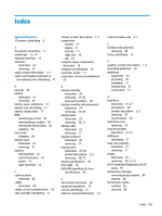
Index Symbols/Numerics 3D camera, identifying 9 A AC adapter and battery 11 action keys 15, 16 airplane mode key 16 antennas illustrated 25 removing 76 audio, product description 3, 7 audio-out (headphone)/audio-in (microphone) jack, identifying 11 B backups 85 battery illustrated 23 removing 34 battery cover, identifying 17 battery lock, identifying 17 battery release latch 17 BIOS determining version 83 downloading an update 84 starting the Setup Utility 83 updating 83 boot order changing 89 bottom cover illustrated 23 removing 41 buttons left TouchPad 12 optical drive eject 10 power 14 right TouchPad 12 C cable locations removing 80 cables illustrated 28 cables, service considerations 29 caps lock light, identifying 13 chipset, product description 1, 5 components bottom 17 display 9 left side 11 right side 10 top 12 computer major components, illustrated 19 computer specifications 93 connector, power 11 connectors, service considerations 29 D display assembly illustrated 20 removing 37, 69 spare part numbers 20 display assembly subcomponents illustrated 24 removing 37, 69 display bezel illustrated 25 removing 38, 71 display cable illustrated 25 removing 77 display enclosure illustrated 25 removing 77 display panel illustrated 25, 69 product description 2, 6 removing 39, 73 display specifications 94 drive light 10 DVD±RW SuperMulti DL Drive specifications 95 E electrostatic discharge 30 equipment guidelines 32 esc key, identifying 15 Ethernet, product description 3, 7 external media cards 4, 7 F fan/heat sink assembly removing 58 fn key, identifying 15 G graphics, product description 1, 5 grounding guidelines 30 guidelines equipment 32 grounding 30 packaging 31 transporting 31 workstation 31 H hard drive illustrated 21, 27 precautions 30 product description 2, 6 removing 43 specifications 94 hard drive cover removing 45 hard drive holder illustrated 21, 27 HDMI port identifying 11 heat sink assembly illustrated 21 removing 21 hinges illustrated 25 removing 39, 73, 75 HP PC Hardware Diagnostics (UEFI) using 91 HP Recovery Manager correcting boot problems 89 starting 88 HP Recovery media creating 85 recovery 88 Index 103
-
 1
1 -
2
-
3
-
4
-
5
-
6
-
7
-
8
-
9
-
10
-
11
-
12
-
13
-
14
-
15
-
16
-
17
-
18
-
19
-
20
-
21
-
22
-
23
-
24
-
25
-
26
-
27
-
28
-
29
-
30
-
31
-
32
-
33
-
34
-
35
-
36
-
37
-
38
-
39
-
40
-
41
-
42
-
43
-
44
-
45
-
46
-
47
-
48
-
49
-
50
-
51
-
52
-
53
-
54
-
55
-
56
-
57
-
58
-
59
-
60
-
61
-
62
-
63
-
64
-
65
-
66
-
67
-
68
-
69
-
70
-
71
-
72
-
73
-
74
-
75
-
76
-
77
-
78
-
79
-
80
-
81
-
82
-
83
-
84
-
85
-
86
-
87
-
88
-
89
-
90
-
91
-
92
-
93
-
94
-
95
-
96
-
97
-
98
-
99
-
100
-
101
-
102
-
103
-
104
-
105
-
 106
106 -
 107
107 -
 108
108 -
 109
109 -
 110
110 -
 111
111 -
 112
112 -
 113
113 -
 114
114
 |
 |