HP 17-x000 17-x099 Models: 17-x100 - 17-x199 - Maintenance and Service Guide - Page 82
that secure the touch control board to the top of the, Remove the two Phillips PM2.0×2.0 screws
 |
View all HP 17-x000 manuals
Add to My Manuals
Save this manual to your list of manuals |
Page 82 highlights
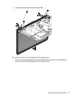
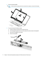
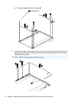
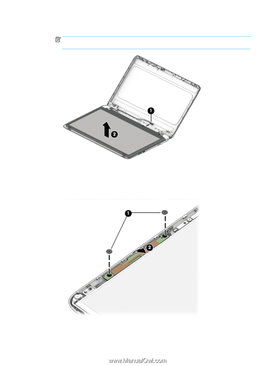
d. Remove the display panel from the computer (2). NOTE: In this procedure the display will not be connected to the computer as shown in the following image. 5. To remove the touch control board from the display: a. Remove the two Phillips PM2.0×2.0 screws (1) that secure the touch control board to the top of the display assembly. b. Rotate the board upside down to access the connectors underneath (2). c. Disconnect the cable from the end of the board (1). 74 Chapter 6 Removal and replacement procedures for Authorized Service Provider parts
-
 1
1 -
2
-
3
-
4
-
5
-
6
-
7
-
8
-
9
-
10
-
11
-
12
-
13
-
14
-
15
-
16
-
17
-
18
-
19
-
20
-
21
-
22
-
23
-
24
-
25
-
26
-
27
-
28
-
29
-
30
-
31
-
32
-
33
-
34
-
35
-
36
-
37
-
38
-
39
-
40
-
41
-
42
-
43
-
44
-
45
-
46
-
47
-
48
-
49
-
50
-
51
-
52
-
53
-
54
-
55
-
56
-
57
-
58
-
59
-
60
-
61
-
62
-
63
-
64
-
65
-
66
-
67
-
68
-
69
-
70
-
71
-
72
-
73
-
74
-
75
-
76
-
 77
77 -
 78
78 -
 79
79 -
 80
80 -
 81
81 -
 82
82 -
 83
83 -
 84
84 -
 85
85 -
 86
86 -
 87
87 -
88
-
89
-
90
-
91
-
92
-
93
-
94
-
95
-
96
-
97
-
98
-
99
-
100
-
101
-
102
-
103
-
104
-
105
-
106
-
107
-
108
-
109
-
110
-
111
-
112
-
113
-
114
 |
 |
d.
Remove the display panel from the computer
(2)
.
NOTE:
In this procedure the display will not be connected to the computer as shown in the
following image.
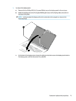
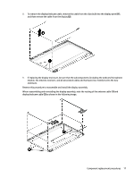
5.
To remove the touch control board from the display:
a.
Remove the two Phillips PM2.0×2.0 screws
(1)
that secure the touch control board to the top of the
display assembly.
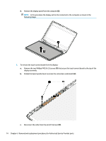
b.
Rotate the board upside down to access the connectors underneath
(2)
.
c.
Disconnect the cable from the end of the board
(1)
.
74
Chapter 6
Removal and replacement procedures for Authorized Service Provider parts