HP 2000-2d20ca HP 2000 Notebook PC and Compaq CQ58 Notebook PC - Maintenance a - Page 64
Optical drive, Remove the Phillips PM2.5×5.0 screw
 |
View all HP 2000-2d20ca manuals
Add to My Manuals
Save this manual to your list of manuals |
Page 64 highlights
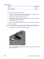
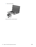
Optical drive NOTE: The optical drive spare part kit includes the rear optical drive bracket but does not include the optical drive cable or cable bracket. The optical drive cable and cable bracket are included in the optical drive cable kit. See Optical drive cable on page 88 for more information about the optical drive cable and cable bracket. Description DVD±RW and CD-RW Super Multi Double-Layer Combo Drive Spare part number 689685-001 Before removing the optical drive, follow these steps: 1. Shut down the computer. If you are unsure whether the computer is off or in Hibernation, turn the computer on, and then shut it down through the operating system. 2. Disconnect all external devices connected to the computer. 3. Disconnect the power from the computer by first unplugging the power cord from the AC outlet and then unplugging the AC adapter from the computer. 4. Remove the battery (see Battery on page 39). 5. Remove the memory module/wireless module compartment cover (see WLAN module on page 48). 6. Remove the hard drive (see Hard drive on page 53). To remove the optical drive: 1. Remove the Phillips PM2.5×5.0 screw (1) that secures the optical drive to the computer. 2. Insert a screwdriver or similar small tool into the hole at the rear of the optical drive bay, and then push the optical drive (2) to release it from the bay. 3. Remove the optical drive (3) by sliding it out of the optical drive bay. 4. If it is necessary to replace the optical drive bracket on the rear of the optical drive, position the optical drive with the rear panel toward you. 56 Chapter 4 Removal and replacement procedures ENWW
-
 1
1 -
2
-
3
-
4
-
5
-
6
-
7
-
8
-
9
-
10
-
11
-
12
-
13
-
14
-
15
-
16
-
17
-
18
-
19
-
20
-
21
-
22
-
23
-
24
-
25
-
26
-
27
-
28
-
29
-
30
-
31
-
32
-
33
-
34
-
35
-
36
-
37
-
38
-
39
-
40
-
41
-
42
-
43
-
44
-
45
-
46
-
47
-
48
-
49
-
50
-
51
-
52
-
53
-
54
-
55
-
56
-
57
-
58
-
 59
59 -
 60
60 -
 61
61 -
 62
62 -
 63
63 -
 64
64 -
 65
65 -
 66
66 -
 67
67 -
 68
68 -
 69
69 -
70
-
71
-
72
-
73
-
74
-
75
-
76
-
77
-
78
-
79
-
80
-
81
-
82
-
83
-
84
-
85
-
86
-
87
-
88
-
89
-
90
-
91
-
92
-
93
-
94
-
95
-
96
-
97
-
98
-
99
-
100
-
101
-
102
-
103
-
104
-
105
-
106
-
107
-
108
-
109
-
110
-
111
-
112
-
113
-
114
-
115
-
116
-
117
-
118
-
119
-
120
-
121
-
122
-
123
-
124
-
125
-
126
-
127
-
128
-
129
-
130
-
131
-
132
-
133
-
134
-
135
-
136
 |
 |
