HP 2000-2d20ca HP 2000 Notebook PC and Compaq CQ58 Notebook PC - Maintenance a - Page 83
Display assembly
 |
View all HP 2000-2d20ca manuals
Add to My Manuals
Save this manual to your list of manuals |
Page 83 highlights
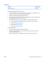
Display assembly This section describes removing the display assembly in its entirety and disassembling all the display subcomponents. If you only need to remove the display bezel, webcam/microphone module, or display panel, you do not need to remove the entire display assembly from the computer. See Display subcomponents (bezel, webcam, panel) on page 40 for more information about removing the display subcomponents that do not require that you remove the entire display assembly from the computer. Description Antennas (includes wireless antenna cables and transceivers; also includes Mylar screw covers) NOTE: Models may have either one or two antennas installed. Display cable (includes display panel cable and webcam/microphone cable; also includes Mylar screw covers) Display enclosure for use in blue HP models (includes Mylar screw covers) Display enclosure for use in black HP models (includes Mylar screw covers) Display enclosure for use in Compaq models (includes Mylar screw covers) Hinges (include hinges and left and right hinge covers) Spare part number 689670-001 689677-001 689671-001 689672-001 689673-001 689679-001 Before removing the display assembly in its entirety, follow these steps: 1. Shut down the computer. If you are unsure whether the computer is off or in Hibernation, turn the computer on, and then shut it down through the operating system. 2. Disconnect all external devices connected to the computer. 3. Disconnect the power from the computer by first unplugging the power cord from the AC outlet and then unplugging the AC adapter from the computer. 4. Remove the battery (see Battery on page 39). 5. Disconnect the WLAN module antenna cables from the WLAN module (see WLAN module on page 48). 6. Remove the following components: ● Hard drive (see Hard drive on page 53) ● Keyboard (see Keyboard on page 58) ● Top cover (see Top cover on page 61) ● USB board (see USB board on page 71) ● Power connector cable (see Power connector cable on page 73) To remove the display assembly in its entirety: 1. Disconnect the display panel cable (1) from the system board. ENWW Component replacement procedures 75
-
 1
1 -
2
-
3
-
4
-
5
-
6
-
7
-
8
-
9
-
10
-
11
-
12
-
13
-
14
-
15
-
16
-
17
-
18
-
19
-
20
-
21
-
22
-
23
-
24
-
25
-
26
-
27
-
28
-
29
-
30
-
31
-
32
-
33
-
34
-
35
-
36
-
37
-
38
-
39
-
40
-
41
-
42
-
43
-
44
-
45
-
46
-
47
-
48
-
49
-
50
-
51
-
52
-
53
-
54
-
55
-
56
-
57
-
58
-
59
-
60
-
61
-
62
-
63
-
64
-
65
-
66
-
67
-
68
-
69
-
70
-
71
-
72
-
73
-
74
-
75
-
76
-
77
-
 78
78 -
 79
79 -
 80
80 -
 81
81 -
 82
82 -
 83
83 -
 84
84 -
 85
85 -
 86
86 -
 87
87 -
 88
88 -
89
-
90
-
91
-
92
-
93
-
94
-
95
-
96
-
97
-
98
-
99
-
100
-
101
-
102
-
103
-
104
-
105
-
106
-
107
-
108
-
109
-
110
-
111
-
112
-
113
-
114
-
115
-
116
-
117
-
118
-
119
-
120
-
121
-
122
-
123
-
124
-
125
-
126
-
127
-
128
-
129
-
130
-
131
-
132
-
133
-
134
-
135
-
136
 |
 |
