HP 2133 HP 2133 Mini-Note PC and HP 2140 Mini-Note PC - Maintenance and Servic - Page 73
Remove the Torx8 T8M2.5×5.0 screw
 |
UPC - 884420156444
View all HP 2133 manuals
Add to My Manuals
Save this manual to your list of manuals |
Page 73 highlights
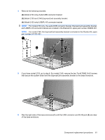
3. Disconnect the power from the computer by first unplugging the power cord from the AC outlet and then unplugging the AC adapter from the computer. 4. Remove the battery (see Battery on page 44). 5. Remove the following components: a. Keyboard (see Keyboard on page 45) b. Hard drive or solid-state drive (see Mass storage device on page 49) c. Top cover (see Top cover on page 52) d. Audio board (see Audio board (Model 2133 only) on page 55) e. System board (see System board on page 59) Remove the WLAN module: CAUTION: To prevent an unresponsive system, replace the wireless module only with a wireless module authorized for use in the computer by the governmental agency that regulates wireless devices in your country or region. If you replace the module and then receive a warning message, remove the module to restore computer functionality, and then contact technical support through Help and Support. 1. Turn the system board upside down, with the front toward you. 2. Remove the Torx8 T8M2.5×5.0 screw (1) that secures the WLAN module to the system board. (The edge of the module opposite the slot rises away from the computer.) 3. Remove the WLAN module (2) by pulling the module away from the slot at an angle. NOTE: WLAN modules are designed with a notch (3) to prevent incorrect insertion. Reverse this procedure to install the WLAN module. Component replacement procedures 65
-
 1
1 -
2
-
3
-
4
-
5
-
6
-
7
-
8
-
9
-
10
-
11
-
12
-
13
-
14
-
15
-
16
-
17
-
18
-
19
-
20
-
21
-
22
-
23
-
24
-
25
-
26
-
27
-
28
-
29
-
30
-
31
-
32
-
33
-
34
-
35
-
36
-
37
-
38
-
39
-
40
-
41
-
42
-
43
-
44
-
45
-
46
-
47
-
48
-
49
-
50
-
51
-
52
-
53
-
54
-
55
-
56
-
57
-
58
-
59
-
60
-
61
-
62
-
63
-
64
-
65
-
66
-
67
-
 68
68 -
 69
69 -
 70
70 -
 71
71 -
 72
72 -
 73
73 -
 74
74 -
 75
75 -
 76
76 -
 77
77 -
 78
78 -
79
-
80
-
81
-
82
-
83
-
84
-
85
-
86
-
87
-
88
-
89
-
90
-
91
-
92
-
93
-
94
-
95
-
96
-
97
-
98
-
99
-
100
-
101
-
102
-
103
-
104
-
105
-
106
-
107
-
108
-
109
-
110
-
111
-
112
-
113
-
114
-
115
-
116
-
117
-
118
-
119
-
120
-
121
-
122
-
123
-
124
-
125
-
126
-
127
-
128
-
129
-
130
 |
 |
