HP 2210b HP Compaq 2210b Notebook PC - Maintenance and Service Guide - Page 73
System board, WLAN module see
 |
View all HP 2210b manuals
Add to My Manuals
Save this manual to your list of manuals |
Page 73 highlights
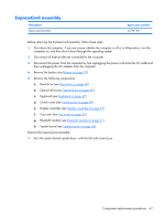
Reverse this procedure to install the microphone. System board Description System board (includes replacement thermal material) Spare part number 453991-001 Before removing the system board, follow these steps: 1. Shut down the computer. If you are unsure whether the computer is off or in Hibernation, turn the computer on, and then shut it down through the operating system. 2. Disconnect all external devices connected to the computer. 3. Disconnect the power from the computer by first unplugging the power cord from the AC outlet and then unplugging the AC adapter from the computer. 4. Remove the battery (see Battery on page 37). 5. Remove the following components: a. Hard drive (see Hard drive on page 38) b. Optical drive (see Optical drive on page 45) c. Keyboard (see Keyboard on page 47) d. Switch cover (see Switch cover on page 49) e. Display assembly (see Display assembly on page 51) f. Top cover (see Top cover on page 55) g. Bluetooth module (see Bluetooth module on page 61) When replacing the system board, be sure that the following components are removed from the defective system board and installed on the replacement system board: ● Memory module (see Memory module on page 40) ● WLAN module (see WLAN module on page 42) ● ExpressCard assembly (see ExpressCard assembly on page 67) ● Modem module (see Modem module on page 69) ● Fan (see Fan on page 71) ● Heat sink (see Heat sink on page 73) ● Processor (see Processor on page 75) Remove the system board: 1. Remove the three Phillips PM2.5×6.0 screws (1) that secure the system board to the base enclosure. Component replacement procedures 65
-
 1
1 -
2
-
3
-
4
-
5
-
6
-
7
-
8
-
9
-
10
-
11
-
12
-
13
-
14
-
15
-
16
-
17
-
18
-
19
-
20
-
21
-
22
-
23
-
24
-
25
-
26
-
27
-
28
-
29
-
30
-
31
-
32
-
33
-
34
-
35
-
36
-
37
-
38
-
39
-
40
-
41
-
42
-
43
-
44
-
45
-
46
-
47
-
48
-
49
-
50
-
51
-
52
-
53
-
54
-
55
-
56
-
57
-
58
-
59
-
60
-
61
-
62
-
63
-
64
-
65
-
66
-
67
-
 68
68 -
 69
69 -
 70
70 -
 71
71 -
 72
72 -
 73
73 -
 74
74 -
 75
75 -
 76
76 -
 77
77 -
 78
78 -
79
-
80
-
81
-
82
-
83
-
84
-
85
-
86
-
87
-
88
-
89
-
90
-
91
-
92
-
93
-
94
-
95
-
96
-
97
-
98
-
99
-
100
-
101
-
102
-
103
-
104
-
105
-
106
-
107
-
108
-
109
-
110
-
111
-
112
-
113
-
114
-
115
-
116
-
117
-
118
-
119
-
120
-
121
-
122
-
123
-
124
-
125
-
126
-
127
-
128
-
129
-
130
-
131
-
132
-
133
-
134
-
135
-
136
-
137
-
138
-
139
-
140
-
141
-
142
-
143
-
144
-
145
-
146
-
147
-
148
-
149
 |
 |
