HP 2730p HP EliteBook 2730p Notebook PC - Maintenance and Service Guide - Page 57
Top cover, Three Torx T8M2.0×8.0 screws.
 |
UPC - 884420401063
View all HP 2730p manuals
Add to My Manuals
Save this manual to your list of manuals |
Page 57 highlights
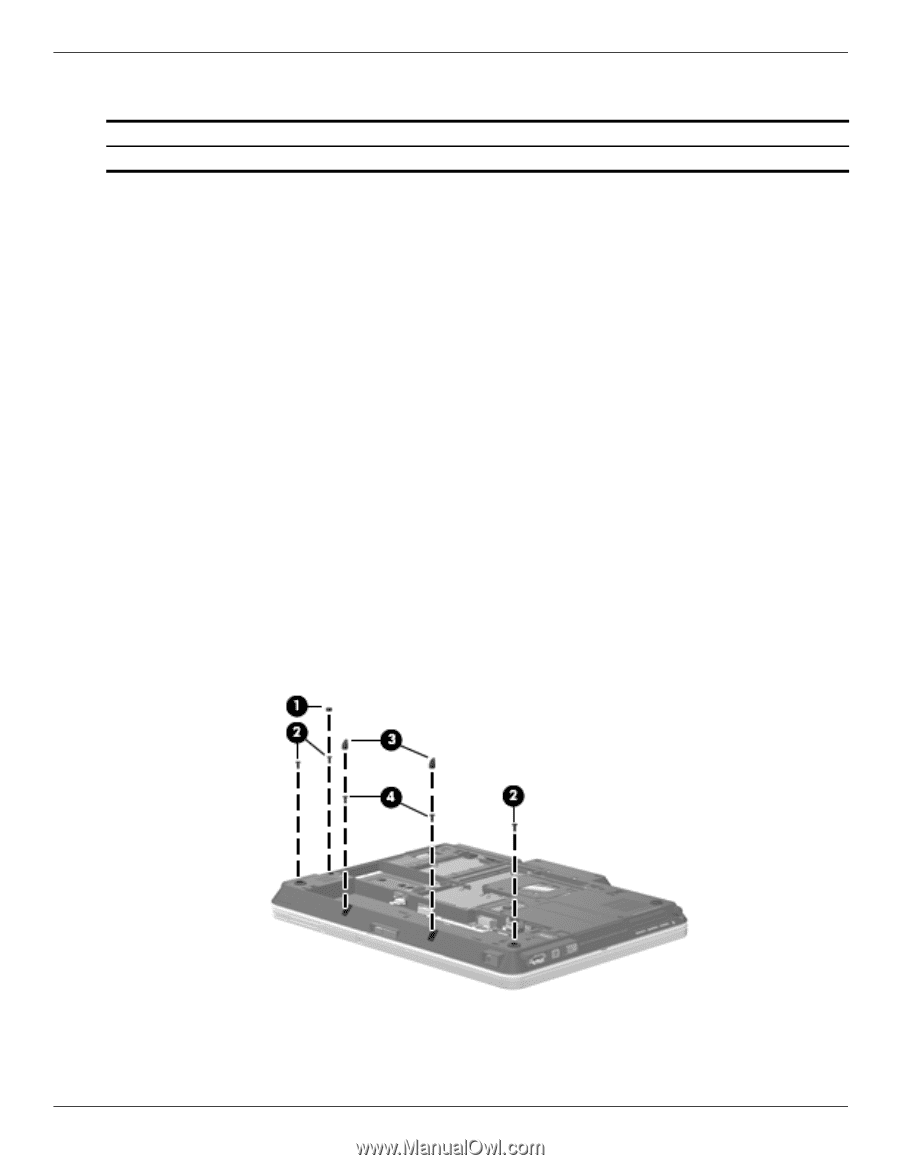
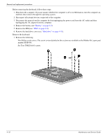
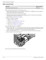
Top cover Removal and replacement procedures Description Top cover (includes LED board and cable and display alignment guides) Spare part number 501502-001 Before removing the top cover, follow these steps: 1. Shut down the computer. If you are unsure whether the computer is off or in Hibernation, turn the computer on, and then shut it down through the operating system. 2. Disconnect all external devices connected to the computer. 3. Disconnect the power from the computer by first unplugging the power cord from the AC outlet and then unplugging the AC adapter from the computer. 4. Remove the battery (see "Battery" on page 4-8). 5. Remove the following components: a. SIM (see "SIM" on page 4-9) b. Hard drive cover (see "Hard drive" on page 4-10) c. Keyboard (see "Keyboard" on page 4-17) d. Hinge cover (see "Hinge cover" on page 4-20) Remove the top cover: 1. Turn the computer upside down, with the front toward you. 2. Remove the following: One small Mylar screw cover. All Mylar screw covers detailed in this section are included in the Rubber Kit, spare part number RUB-001. Three Torx T8M2.0×8.0 screws. Two large Mylar screw covers. The screw covers detailed in this section are included in the Rubber Kit, spare part number RUB-001. Two Torx T8M2.0×4.0 screws. Maintenance and Service Guide 4-21
-
 1
1 -
2
-
3
-
4
-
5
-
6
-
7
-
8
-
9
-
10
-
11
-
12
-
13
-
14
-
15
-
16
-
17
-
18
-
19
-
20
-
21
-
22
-
23
-
24
-
25
-
26
-
27
-
28
-
29
-
30
-
31
-
32
-
33
-
34
-
35
-
36
-
37
-
38
-
39
-
40
-
41
-
42
-
43
-
44
-
45
-
46
-
47
-
48
-
49
-
50
-
51
-
 52
52 -
 53
53 -
 54
54 -
 55
55 -
 56
56 -
 57
57 -
 58
58 -
 59
59 -
 60
60 -
 61
61 -
 62
62 -
63
-
64
-
65
-
66
-
67
-
68
-
69
-
70
-
71
-
72
-
73
-
74
-
75
-
76
-
77
-
78
-
79
-
80
-
81
-
82
-
83
-
84
-
85
-
86
-
87
-
88
-
89
-
90
-
91
-
92
-
93
-
94
-
95
-
96
-
97
-
98
-
99
-
100
-
101
-
102
-
103
-
104
-
105
-
106
-
107
-
108
-
109
-
110
-
111
-
112
-
113
-
114
-
115
-
116
-
117
-
118
-
119
-
120
-
121
 |
 |