HP 6100 HP 4x00/6x00/8x00 Enterprise Virtual Array User Guide (5697-0733, Marc - Page 122
B EMU-generated condition reports, Condition report format, Correcting errors
 |
View all HP 6100 manuals
Add to My Manuals
Save this manual to your list of manuals |
Page 122 highlights
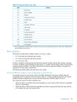
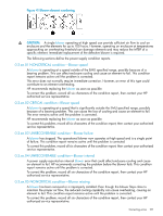
B EMU-generated condition reports This section provides a description of the EMU generated condition reports that contain the following information: • Element type (et), a hexadecimal number in the range 01 through FF. • Element number (en), a decimal number in the range 00 through 99 that identifies the specific element with a problem. • Error code (ec), a decimal number in the range 00 through 99 that defines a specific problem. • The recommended corrective action. NOTE: The conventions used to differentiate between the elements of the condition report are: • Element type-period after each character • Element number-period after the second character • Error code-no periods The EMU can send error messages to the controller for transmission to HP Command View EVA. The messages displayed are specific to HP Command View EVA and are not within the scope of this publication. The I/O modules have the built-in intelligence to: • Observe fibre channel events • Bypass drive ports based on events • Perform drive port testing and monitoring to prevent poor-performing drives from participating in the loop • Communicate fibre channel events to the controllers This appendix explains the condition report format, correcting problems, and how to identify element types. The error codes are arranged in element type sequence (that is, 0.1., 0.2., 0.3., etc.). Condition report format When the EMU alphanumeric display is Er, three additional displays identify the possible cause of the problem: the element type, the specific element, and the error code, which defines the possible cause of the problem. • The first-level display identifies the type of element affected with two alphanumeric characters separated by periods such as 0.1., 0.2., 1.3., F.F., and so forth. A disk drive problem would display an element type number of 0.1. • The second-level display identifies the element affected with a two-digit, decimal number followed by a period. For example, when a bay 6 drive error occurs, the element number display is 06.; a display of 14. indicates a bay 14 problem. • The third-level display identifies a specific problem, the error code with a two-digit, decimal number. For example, should the problem be either the installation of an incorrectly configured drive or one that cannot operate at the loop link rate, the display is 01. Correcting errors Correcting an error may require you to perform a specific set of actions. In some cases, the only available corrective action is to replace the element. Table 42 (page 123) lists the element type codes assigned to the drive enclosure elements. 122 EMU-generated condition reports
-
 1
1 -
2
-
3
-
4
-
5
-
6
-
7
-
8
-
9
-
10
-
11
-
12
-
13
-
14
-
15
-
16
-
17
-
18
-
19
-
20
-
21
-
22
-
23
-
24
-
25
-
26
-
27
-
28
-
29
-
30
-
31
-
32
-
33
-
34
-
35
-
36
-
37
-
38
-
39
-
40
-
41
-
42
-
43
-
44
-
45
-
46
-
47
-
48
-
49
-
50
-
51
-
52
-
53
-
54
-
55
-
56
-
57
-
58
-
59
-
60
-
61
-
62
-
63
-
64
-
65
-
66
-
67
-
68
-
69
-
70
-
71
-
72
-
73
-
74
-
75
-
76
-
77
-
78
-
79
-
80
-
81
-
82
-
83
-
84
-
85
-
86
-
87
-
88
-
89
-
90
-
91
-
92
-
93
-
94
-
95
-
96
-
97
-
98
-
99
-
100
-
101
-
102
-
103
-
104
-
105
-
106
-
107
-
108
-
109
-
110
-
111
-
112
-
113
-
114
-
115
-
116
-
 117
117 -
 118
118 -
 119
119 -
 120
120 -
 121
121 -
 122
122 -
 123
123 -
 124
124 -
 125
125 -
 126
126 -
 127
127 -
128
-
129
-
130
-
131
-
132
-
133
-
134
-
135
-
136
-
137
-
138
-
139
-
140
-
141
-
142
-
143
-
144
-
145
-
146
-
147
-
148
-
149
-
150
-
151
-
152
-
153
-
154
-
155
-
156
-
157
-
158
-
159
-
160
-
161
-
162
-
163
-
164
-
165
-
166
-
167
-
168
-
169
-
170
-
171
-
172
-
173
-
174
-
175
-
176
-
177
-
178
-
179
-
180
-
181
-
182
-
183
-
184
-
185
 |
 |
