HP 6100 HP 4x00/6x00/8x00 Enterprise Virtual Array User Guide (5697-0733, Marc - Page 9
C Controller fault management, D Non-standard rack specifications, E Single Path Implementation
 |
View all HP 6100 manuals
Add to My Manuals
Save this manual to your list of manuals |
Page 9 highlights
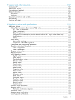
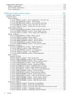
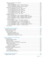
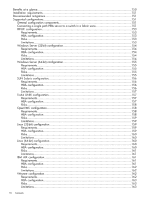
CAN bus communication port conditions 135 Resetting the EMU...135 1.1.03.01 NONCRITICAL condition-Communication error 135 1.1.03.02 INFORMATION condition-Recovery completed 136 1.1.03.03 INFORMATION condition-Overrun recovery 136 Voltage sensor and current sensor conditions 136 1.2.en.01 NONCRITICAL condition-High voltage 136 1.2.en.02 CRITICAL condition-High voltage 136 1.2.en.03 NONCRITICAL condition-Low voltage 137 1.2.en.04 CRITICAL condition-Low voltage 137 1.3.en.01 NONCRITICAL condition-High current 137 1.3.en.02 CRITICAL condition-High current 137 Backplane conditions...137 8.2.01.10 NONCRITICAL condition-Backplane NVRAM read 137 8.2.01.11 NONCRITICAL condition-Backplane NVRAM write failure 137 8.2.01.12 NONCRITICAL condition-Backplane NVRAM read failure 138 8.2.01.13 NONCRITICAL condition-Backplane WWN is blank 138 I/O Module conditions...138 8.7.en.01 CRITICAL condition-I/O module unsupported 138 8.7.en.02 CRITICAL condition-I/O module communication 138 8.7.en.10 NONCRITICAL condition-I/O module NVRAM read 138 8.7.en.11 NONCRITICAL condition-I/O module NVRAM write 139 8.7.en.12 NONCRITICAL condition-I/O Module NVRAM read failure 139 8.7.en.13 NONCRITICAL condition-I/O module removed 139 Host conditions...139 C Controller fault management 140 Using HP Command View EVA 140 GUI termination event display 140 GUI event display...140 Fault management displays 141 Displaying Last Fault Information 141 Displaying Detailed Information 141 Interpreting fault management information 142 D Non-standard rack specifications 143 Rack specifications...143 Internal component envelope 143 EIA310-D standards...143 EVA cabinet measures and tolerances 143 Weights, dimensions and component CG measurements 143 Airflow and Recirculation 144 Component Airflow Requirements 144 Rack Airflow Requirements 144 Configuration Standards 144 Environmental and operating specifications 145 Power requirements...145 UPS Selection...146 Environmental specifications 148 Shock and vibration specifications 149 E Single Path Implementation 150 High-level solution overview 150 Contents 9
-
 1
1 -
2
-
3
-
 4
4 -
 5
5 -
 6
6 -
 7
7 -
 8
8 -
 9
9 -
 10
10 -
 11
11 -
 12
12 -
 13
13 -
 14
14 -
15
-
16
-
17
-
18
-
19
-
20
-
21
-
22
-
23
-
24
-
25
-
26
-
27
-
28
-
29
-
30
-
31
-
32
-
33
-
34
-
35
-
36
-
37
-
38
-
39
-
40
-
41
-
42
-
43
-
44
-
45
-
46
-
47
-
48
-
49
-
50
-
51
-
52
-
53
-
54
-
55
-
56
-
57
-
58
-
59
-
60
-
61
-
62
-
63
-
64
-
65
-
66
-
67
-
68
-
69
-
70
-
71
-
72
-
73
-
74
-
75
-
76
-
77
-
78
-
79
-
80
-
81
-
82
-
83
-
84
-
85
-
86
-
87
-
88
-
89
-
90
-
91
-
92
-
93
-
94
-
95
-
96
-
97
-
98
-
99
-
100
-
101
-
102
-
103
-
104
-
105
-
106
-
107
-
108
-
109
-
110
-
111
-
112
-
113
-
114
-
115
-
116
-
117
-
118
-
119
-
120
-
121
-
122
-
123
-
124
-
125
-
126
-
127
-
128
-
129
-
130
-
131
-
132
-
133
-
134
-
135
-
136
-
137
-
138
-
139
-
140
-
141
-
142
-
143
-
144
-
145
-
146
-
147
-
148
-
149
-
150
-
151
-
152
-
153
-
154
-
155
-
156
-
157
-
158
-
159
-
160
-
161
-
162
-
163
-
164
-
165
-
166
-
167
-
168
-
169
-
170
-
171
-
172
-
173
-
174
-
175
-
176
-
177
-
178
-
179
-
180
-
181
-
182
-
183
-
184
-
185
 |
 |
