HP 6720s HP Compaq 6720s Notebook PC - Maintenance and Service Guide - Page 152
legacy support, Universal Serial Bus, DVD/CD-RW Combo Drive
 |
UPC - 883585979370
View all HP 6720s manuals
Add to My Manuals
Save this manual to your list of manuals |
Page 152 highlights
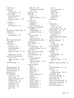
display panel product description 2 removal 57 display specifications 87 DriveLock password 83 drives boot order 84 preventing damage 32 DVD/CD-RW Combo Drive precautions 32 removal 46 spare part number 20, 23, 29, 46 specifications 90 DVD±RW and CD-RW Combo Drive precautions 32 removal 46 spare part numbers 19, 23, 29, 46 specifications 89 E electrostatic discharge 33 entire hard drive backup 126 esc key 8 Ethernet, product description 4 Execution Disable 84 ExpressCard assembly removal 78 spare part number 16, 28, 78 ExpressCard slot 11 ExpressCard slot bezel, illustrated 21 external media cards, product description 4 external monitor port location 11 pin assignments 132 F fan removal 69 spare part number 69 feet locations 38 spare part number File menu 82 fn key 8 16, 25, 38 front components 9 function keys 8 G graphics, product description 2 grounding equipment and methods 35 H hard drive location 12 precautions 32 product description 3 removal 40 spare part numbers 19, 23, 29, 40 specifications 88 hard drive backup 120, 126 hard drive bay 12 hard drive bay cover illustrated 21 removal 40 hard drive bracket, removal 41 hard drive recovery 122, 128 hard drive test 83 headphone jack location 9 pin assignments 131 heat sink removal 71 spare part number 16, 28, 71 hinge removal 58 spare part number 15, 29, 58 I I/O address specifications 93 interrupt specifications 92 J jacks audio-in 9 audio-out 9 headphone 9 microphone 9 modem 11 network 11 RJ-11 11 RJ-45 11 K key components 8 keyboard product description 4 removal 50 spare part numbers 15, 28, 50 keypad keys 8 keys esc 8 fn 8 function 8 keypad 8 Windows applications 8 Windows logo 8 L LAN Power Save 84 language, changing in Computer Setup 84 left-side components 11 legacy support, Universal Serial Bus (USB) 80, 84 light components 7 lights battery 11 caps lock 7 optical drive 10 power 8 wireless 7 Logo Kit, spare part number 24, 28 M mass storage devices, spare part numbers 23 memory check 83 memory map specifications 95 memory module product description 2 removal 45 spare part numbers 19, 25, 45 memory module compartment 12 memory module compartment cover illustrated 21 removal 45 microphone jack location 9 pin assignments 131 144 Index
-
 1
1 -
2
-
3
-
4
-
5
-
6
-
7
-
8
-
9
-
10
-
11
-
12
-
13
-
14
-
15
-
16
-
17
-
18
-
19
-
20
-
21
-
22
-
23
-
24
-
25
-
26
-
27
-
28
-
29
-
30
-
31
-
32
-
33
-
34
-
35
-
36
-
37
-
38
-
39
-
40
-
41
-
42
-
43
-
44
-
45
-
46
-
47
-
48
-
49
-
50
-
51
-
52
-
53
-
54
-
55
-
56
-
57
-
58
-
59
-
60
-
61
-
62
-
63
-
64
-
65
-
66
-
67
-
68
-
69
-
70
-
71
-
72
-
73
-
74
-
75
-
76
-
77
-
78
-
79
-
80
-
81
-
82
-
83
-
84
-
85
-
86
-
87
-
88
-
89
-
90
-
91
-
92
-
93
-
94
-
95
-
96
-
97
-
98
-
99
-
100
-
101
-
102
-
103
-
104
-
105
-
106
-
107
-
108
-
109
-
110
-
111
-
112
-
113
-
114
-
115
-
116
-
117
-
118
-
119
-
120
-
121
-
122
-
123
-
124
-
125
-
126
-
127
-
128
-
129
-
130
-
131
-
132
-
133
-
134
-
135
-
136
-
137
-
138
-
139
-
140
-
141
-
142
-
143
-
144
-
145
-
146
-
 147
147 -
 148
148 -
 149
149 -
 150
150 -
 151
151 -
 152
152 -
 153
153 -
 154
154 -
 155
155
 |
 |